
Summary of Contents for Emerson Liebert NXC
- Page 1 AC Power for Business-Critical Continuity ™ Liebert ® f rom 10 to 20kVA User Manual...
- Page 2 Liebert NXC 10/15/20kVA UNINTERRUPTIBLE POWER SUPPLY USER MANUAL 10H52188UM60 - rev. 2...
- Page 3 All rights, including rights created by patent grant or registration of utility model or design, are reserved. Delivery subject to availability. Right of technical modification reserved. Liebert NXC may differ from the one displayed on the front cover. User Manual 10H52188UM60 - Rev. 2 - 09/2012...
-
Page 4: Table Of Contents
Liebert NXC Contents Contents CHAPTER 1 PRODUCT INTRODUCTION ....................5 1.1 Features ..............................5 1.2 Model Configurations ..........................5 1.3 Appearance And Components ......................... 6 1.3.1 Appearance ............................. 6 1.3.2 Components ............................ 6 ... - Page 5 10.2 Communication Cables ........................64 10.3 Battery Cabinet ............................ 64 10.4 Liebert NXC Input Transformer Version ....................65 10.5 Liebert NXC Output Transformer Version ..................... 65 APPENDIX 1 ABBREVIATIONS ........................ 66 APPENDIX 2 INFORMATION FOR THE PROTECTION OF THE ENVIRONMENT ..........67...
-
Page 6: Chapter 1 Product Introduction
Chapter 1 Product Introduction Liebert NXC UPS (UPS for short) is an intelligent online UPS system with sine wave output developed by Emerson Network Power. The UPS offers reliable and high quality AC power to the precision instrument. The UPS is suitable for supplying AC power to small scale computer centers, networks, communication systems, automatic control systems and precision instruments. -
Page 7: Appearance And Components
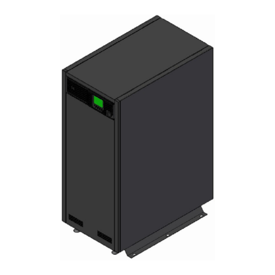
Product Introduction Liebert NXC 1.3 Appearance And Components 1.3.1 Appearance The UPS device appearance is shown in Figure 1-1. Front view Rear view Figure 1-1 UPS appearance 1.3.2 Components UPS module front panel As shown in Figure 1-2, the UPS module front panel provides ventilation holes, operation and display panel, LED indicators, DIP switch and battery cold start button. - Page 8 Liebert NX Product Introduction UPS module rear panel As shown in Figure 1-3 and Figure 1-4, the UPS module rear panel provides parallel ports, Load Bus Synchronization (LBS) ports, Intellislot cards port, dry contact ports, opto-coupled ports, USB port and ventilation holes. The SIC-SNMP card in the Intellislot cards port is optional, it is sold separately.
-
Page 9: Ups Device Rear
Product Introduction Liebert NXC 1.3.3 UPS device rear As shown in Figure 1-5, the UPS comprises UPS module, Input/Output MCBs and I/O terminal block. UPS MODULE QS4 (UPS OUTPUT) QS3 (MAINTENANCE BYPASS) INPUT/OUTPUT MCBs QS6/7 (INTERNAL BATTERY) QS1 (PRIMARY MAINS INPUT) -
Page 10: Operating Principle
Liebert NX Product Introduction 1.4 Operating Principle The operating principle of the UPS is shown in Figure 1-6. Bypass input Bypass Input filter Output Output filter Mains input Inverter Rectifier/PFC Auxiliary power Charger Battery controller Figure 1-6 UPS operating principle 1. -
Page 11: Ups State And Operation Mode
Product Introduction Liebert NXC 1.5 UPS State And Operation Mode The UPS state and operation mode include: Normal mode, Bypass mode, Battery mode, FRC (Frequency Converter) mode, ECO mode, Fault state and Maintenance Bypass mode. The operation schematic diagrams of Normal mode, Bypass mode, Battery mode, Maintenance Bypass mode, ECO mode and FRC mode are shown in Figure 1-7. -
Page 12: Normal Mode
Liebert NX Product Introduction 1.5.1 Normal Mode When the mains input is normal, the load is provided with voltage-stabilized and frequency- stabilized power by the inverter, and meanwhile the battery is charged. In Normal mode, the inverter indicators are on (green). 1.5.2 Bypass Mode If the overload time-out, inverter or rectifier failure appears during the UPS operation in Normal mode, the UPS will transfer to Bypass mode, that is, the load is powered by the bypass source, which comes directly from the mains input;... -
Page 13: Maintenance Bypass Mode
Note If the UPS has a malfunctions and can not work normally, please get in touch with the nearest Emerson branch office or local service center. It is prohibited to repaire by yourself, as the personnel injury and damage to the equipment may occur. -
Page 14: Chapter 2 Battery
Liebert NXC Battery Chapter 2 Battery This chapter provides relevant information about the battery, including a short introduction, and information on battery safety, battery power cables, battery maintenance and recycling. 2.1 Brief Introduction The UPS battery string consists of batteries connected in series in order to supply the rated DC input voltage for the UPS inverter. -
Page 15: Battery Power Cable
Battery Liebert NXC Warning: Hazardous battery voltage present behind covers 1. No user-serviceable parts are located behind covers that require a tool for their removal. Only qualified service personnel are authorized to remove such covers. 2. Before working on the copper bars connected to the external battery, please ensure they are disconnected from all power supplies. -
Page 16: Connecting The Batteries
Liebert NXC Battery 6. In the case of a parallel UPS system that uses a common battery bank, an additional isolating device (switch) must be installed in the dedicated common battery connection to each individual UPS, so that system maintenance can be carried out correctly. - Page 17 Battery Liebert NXC ARRANGE THE BATTERIES AND CONNECT THEM AS ILLUSTRATED IN Figure 2-1. TOP VIEW BATTERY 1 BATTERY 2 BATTERY SHELF BATTERY 3 BATTERY 4 BATTERY 5 BATTERY 6 BATTERY 7 BATTERY 8 FRONT Figure 2-1 Internal Battery Cable Connection...
- Page 18 Liebert NXC Battery CONNECT THE BATTERY CABLES AS ILLUSTRATED IN Figure 2-2. XBS15 XBS16 BATTERY STRING 4 XBS13 XBS14 XBS11 XBS12 BATTERY STRING 3 XBS9 XBS10 XBS7 XBS8 BATTERY STRING 2 XBS5 XBS6 XBS3 XBS4 BATTERY STRING 1 XBS1 XBS2 Figure 2-2 Internal Battery Cable Connection For safety reasons, a female connector has been inserted on male connector of battery shelf;...
-
Page 19: Battery Maintenance
For detailed information about Emerson's disused battery recycling system, please consult the local customer service center or Emerson sales office. If the customer disregards these instructions or does not use Emerson's disused battery recycling system, Emerson cannot be held responsible for any environmental consequences of the failure to dispose of disused battery products correctly. -
Page 20: Chapter 3 Single Ups Installation And Commissioning
The UPS should be installed by a qualified engineer according to the information contained in this chapter. If any problem is found, please get in touch with Emerson local service center immediately. The UPS shall not be powered on without approval of the commissioning engineer. -
Page 21: Location
Single UPS Installation And Commissioning Liebert NXC Brake Pad: with 19mm wrench in clockwise direction to screw the Brake Pads down to the ground, to prevent the UPS moving. 3.2.1 Location To extend the UPS life, the place chosen must offer: ... -
Page 22: Installation Tools
Liebert NXC Single UPS Installation And Commissioning Note: for exchanging the UPS Power Module or the Battery Tray front clearance of 950mm is necessary. General view Figure 3-1 Installation clearances Note The UPS should be installed only on the concrete surface or other non-flammable surfaces. -
Page 23: External Protection Devices
Single UPS Installation And Commissioning Liebert NXC 3.3 External protection devices This device is equipped with manual switches intended only for Service Bypass and Internal Service operations. It is therefore essential that the customer install external protection devices at the installation site. These must be installed near the unit and labeled as the line power separation device for the UPS (see IEC/EN 62040-1). - Page 24 Liebert NXC Single UPS Installation And Commissioning Figure 3-2 External protective device for backfeed protection Earth leakage current The residual current detector (RCD) for the UPS upstream input power distribution should be: Sensitive to the DC unidirectional pulse (level A) in power distribution network ...
-
Page 25: Battery Input (For External Battery)
The overcurrent protective device has been placed in the battery cabinet, when you choose the battery cabinet option provided by Emerson. Otherwise, the external battery cabinet should provide DC compatible fused circuit breaker, so as to provide the overcurrent protection for the UPS and its batteries. -
Page 26: Connecting I/O Cables
Liebert NXC Single UPS Installation And Commissioning 3.4.1 Connecting I/O Cables The power cables of the UPS should be connected through the I/O terminal block located on the UPS rear panel. Figure 3-4 gives the terminal layout of the I/O terminal block. - Page 27 Single UPS Installation And Commissioning Liebert NXC Figure 3-5 3-in 3-out, common source configuration cable connection 3-in 3-out, split-bypass configuration 1. Remove all the copper shorting bars 3 from the UPS I/O terminal block. 2. Connect the live lines (mains input phase L1, mains input phase L2 and mains input phase L3), N line and PE line respectively to the I/O terminal block (U1, V1, W1 and N1 and PE terminals) of the UPS.
- Page 28 Liebert NXC Single UPS Installation And Commissioning Figure 3-6 3-in 3-out, split-bypass configuration cable connection 3-in 1-out, common source configuration Warning The factory default of this UPS is 3-in 3-out, common source configuration. Change the power distribution mode of the UPS to 3-in 1-out according to the steps described in the following section Changing power distribution mode.
- Page 29 Single UPS Installation And Commissioning Liebert NXC Figure 3-8 3-in 1-out, common source configuration cable connection 4. Connect the copper shorting bar 8 to one end of the copper shorting bar 7 (see Figure 3-8), and connect the live line (input phase L1) to the copper shorting bar 8.
- Page 30 Liebert NXC Single UPS Installation And Commissioning Figure 3-9 3-in 1-out, split-bypass configuration cable connection 4. Connect the live lines (input phase L1, L2 and input phase L3), N line and PE line respectively to the I/O terminal block (U1, V1 and W1 terminals) of the UPS, one screw hole of the copper shorting bar 4 with N1 and N2 terminals, and one screw hole of the copper shorting bar 10.
-
Page 31: Connecting And Installing External Battery
4. Power off the system completely, replace the EPO jumpers of the dry contact port 4, and remove the main input cable. 3.4.2 Connecting and Installing External Battery Notes For the installation and commissioning of an external Battery, refer to “Liebert NXC Battery User Manual”. User Manual 10H52188UM60 - Rev. 2 - 09/2012... -
Page 32: Single Ups Commissioning
Liebert NXC Single UPS Installation And Commissioning 3.5 Single UPS Commissioning 3.5.1 Check Before Power-On 1. Check and confirm that the power distribution mode of the UPS is correct, that the connections of the power cable and signal cable are correct and there is no short circuit. - Page 33 Single UPS Installation And Commissioning Liebert NXC Table 3-5 Parameter descriptions and default values Display Parameters Notes Default value ParamSet Setting Display contrast Adjust the LCD contrast Date format set M/D/Y, D/M/Y and Y/M/D formats can be selected Y/M/D Date & time...
-
Page 34: Normal Mode Start-Up
Liebert NXC Single UPS Installation And Commissioning Select “Enabled” in “Shared Battery” according to whether the battery is shared. Set “System Configuration” to “Single” if the system is single system. Select “Normal” or “ECO” according to the UPS working mode, select “50Hz” or “60Hz” in “Output Frequency Level”... -
Page 35: Chapter 4 Parallel Ups Installation And Commissioning
Parallel UPS Installation And Commissioning Liebert NXC Chapter 4 Parallel UPS Installation And Commissioning This chapter describes the features, requirements, installation and commissioning of the parallel system. The UPS parallel system provides the user with N + X (2 ≤ N + X ≤ 4) parallel configuration, N stands for the basic parallel sets, X stands for the redundant sets. - Page 36 Liebert NXC Parallel UPS Installation And Commissioning The diagram of three UPS parallel system is shown in Figure 4-1. Refer to Power distribution mode in 3.4.1 for the cable connection of each UPS. Refer to 3.4 for the measurement of the input, output and battery cables.
-
Page 37: Connecting Parallel Cables
Figure 4-2 Cable connection schematic diagram of 3 + 1 parallel system Note 1. The Emerson parallel cables must be used for the parallel system. 2. The parallel communication fault occurs when carrying out the parallel commissioning, check whether the connection of the parallel cables is correct, and whether the pin1~ pin9 are connected. -
Page 38: Connecting External Battery Cables
Liebert NXC Parallel UPS Installation And Commissioning Warning 1. The default setting for DIP switch is ‘1’. However, you should set the DIP switch position for the parallel system according to the description listed in Table 4-1. Otherwise, the UPS fault will occur. - Page 39 Parallel UPS Installation And Commissioning Liebert NXC ‘Bat -’ and ‘PE’ terminals of the corresponding UPS I/O terminal block in parallel system through each battery MCB, as shown in Figure 4-4. UPS 1 UPS 2 Bat+ Bat N Bat- Bat+ Bat N Bat- PE...
-
Page 40: Commissioning Parallel System
Liebert NXC Parallel UPS Installation And Commissioning 4.4 Commissioning Parallel System 4.4.1 Check Before Power-On 1. Check and confirm that the power distribution mode of the UPS is correct; that the connections of the power cables and signals cable are correct and there is no short circuit. -
Page 41: Power-On Commissioning For Parallel System
Parallel UPS Installation And Commissioning Liebert NXC 4.4.3 Power-On Commissioning For Parallel System Power on and commission each UPS of the parallel system respectively, namely power on one UPS at a time, and other UPS are in the powered- down status, the specific commissioning procedures are as follows: 1) Close the external output MCB and input MCB of one UPS, the UPS is powered on. -
Page 42: Installing External Protective Device
Liebert NXC Parallel UPS Installation And Commissioning The double bus system uses the LBS system to realize the output synchronization of the two independent (or parallel) UPS systems. One is the master system, and the other is the slave system. The operation mode of the double bus system contains master system and/or slave system running in normal mode or bypass mode. -
Page 43: Setting Up The Double Bus System Parameters
Parallel UPS Installation And Commissioning Liebert NXC DB9 male port DB9 male port DB9 female port DB9 female port oN oN oA oB oC PE PE UPS 1 UPS 1 DB9 male port DB9 female port DB9 male port DB9 female port... -
Page 44: Chapter 5 Operation And Display Panel
Liebert NXC Operation And Display Panel Chapter 5 Operation And Display Panel This chapter introduces the functions and use of the components on the UPS operation and display panel, and provides LCD display information, including the LCD screen types, detailed menu messages, prompt windows message and UPS alarm list. -
Page 45: Control Buttons
Operation And Display Panel Liebert NXC 5.1.3 Control Buttons The operation and display panel provides five control buttons, the functions of which are described in Table 5-3. Table 5-3 Description of control buttons Control button Silk print Description Used to disconnect the load power and close the rectifier, inverter, static bypass... -
Page 46: Primary Screen
Liebert NXC Operation And Display Panel 5.2.2 Primary Screen After the UPS system self-test, the primary screen shown in Figure 5-3 will appear. The primary screen is composed of four windows: system information window, data window, menu window and keypad window. -
Page 47: Detailed Description Of Menu Items
Table 5-5 System information window Item Explanation Liebert NXC 020kVA UPS name, which stands for Liebert Liebert NXC 20kVA UPS ® 12: 30: 36 Current time (format: 24 Hours, h: min: s) Menu window and data window The menu window displays the menu name of the data window. The data window displays the items of the menu selected from the menu window. - Page 48 Liebert NXC Operation And Display Panel Display Menu Item Explanation ParamSet Setting Display contrast Adjust the LCD contrast MM DD YYYY, DD MM YYYY and YYYY MM DD formats can be Date format set selected Date & time Set the date and time...
-
Page 49: Prompt Window
Operation And Display Panel Liebert NXC 5.4 Prompt Window A prompt window is displayed during the operation of the system to alert you to certain conditions and/or to require your confirmation of a command. The prompts and meanings are given in Table 5-7. - Page 50 Liebert NXC Operation And Display Panel Alarm message Description This alarm is triggered by an inverter software program when the amplitude or frequency of bypass voltage is beyond the normal range. The amplitude threshold is fixed at ±10% of nominal rating.
- Page 51 (3-in 3-out or 3-in 1-out) Note: If the alarm is caused through setting the software value by Emerson authorized engineer, and you wish to change the setting values, please get in touch with the Emerson local customer service center...
-
Page 52: Chapter 6 Ups Operation Instructions
Liebert NXC UPS Operation Instructions Chapter 6 UPS Operation Instructions This chapter gives a detailed description of the UPS operation procedures. During the operation, the buzzer alarm may appear, at this point, you can press the ALARM CLEAR button to silence the audible alarm. -
Page 53: Transfer From Maintenance Bypass Mode To Inverter Mode
UPS Operation Instructions Liebert NXC Caution Before performing this procedure, you should check the LED information first, and make sure the bypass is normal and inverter synchronized. Otherwise, it may result in the load power interruption for a while. 1. Press the OFF for 2 seconds. -
Page 54: Ups Complete Shutdown
Liebert NXC UPS Operation Instructions 6.3 UPS Complete Shutdown If you need to shut down the UPS completely, transfer the UPS from Inverter mode to Maintenance Bypass mode according to the procedures in 6.2.4, so as not to effect the load during the UPS power-off. Then if the power to the load is not needed, open the maintenance bypass MCB directly, as shown in Figure 6-1. -
Page 55: Ups Reset
UPS Operation Instructions Liebert NXC 6.6 UPS Reset The EPO action or the following reasons such as inverter overtemperature, power-off overload, battery overvoltage and excessive switching may result in the UPS power-off. After all appropriate measures have been taken to clear the faults indicated by the alarm message appearing on the LCD, you can carry out the following steps to restore the UPS to normal operation state. -
Page 56: Chapter 7 Communication
Liebert NXC Communication Chapter 7 Communication This chapter briefly introduces the UPS communication. The communication ports include: Intellislot cards port, opto-coupled port, dry contact port and USB port. 7.1 Installing Intellislot cards 7.1.1 Intellislot card Port UPS provides an Intellislot card port (see Figure 7-1), which is used to install the communication device options, including global connectivity cards and LIFE.net adapter. - Page 57 Communication Liebert NXC Description of the dry contact ports Silk print Port name Pin NO. Pin name Meaning S_ALARM The signal level is 12V when the system alarms Output port of alarm ON_BATTERY The signal level is 12V when the system runs in battery mode...
-
Page 58: Connecting Usb Communication Cables
Liebert NXC Communication Note 1. It is recommended to use 0.82mm ~ 0.33mm (signal cable of 18AWG ~ 33AWG) copper core cable. 2. If the switch you have configured is of electronic control tripping function, when the REPO signal takes action, you need to close the switch before restart the UPS. -
Page 59: Chapter 8 Maintenance
Contact Emerson or the nearest service center for the detailed information of the recycle system about the waste battery. Emerson is not liable for the environment results caused by failure to comply with the notices in this section or to use the waste battery recycle system provided by Emerson. -
Page 60: Cleaning Ups
Liebert NXC Maintenance 8.3 Cleaning UPS Clean the UPS periodically, especially the ventilation holes, to ensure free airflow inside the UPS. If necessary, clean the UPS with a vacuum cleaner. Confirm that the ventilation holes are unobstructed. 8.4 Checking UPS State It is recommended to check the UPS operation status once every half year. -
Page 61: Chapter 9 Product Specifications
Product Specifications Liebert NXC Chapter 9 Product Specifications The chapter lists the UPS specifications. 9.1 Conformity and Standards The UPS has been designed to conform to the European and international standards listed in Table 9-1. Table 9-1 European and International Standards... -
Page 62: Electrical Characteristics (Input Rectifier)
Liebert NXC Product Specifications 9.4 Electrical Characteristics (Input Rectifier) Table 9-4 Rectifier AC Input (Mains) Rated power (kVA) Item Unit Rated AC input voltage 380/400/415; default 400 Frequency 40...70 kW/kVA, Power factor full load; >0.99 @ full load; > 0.98 @ half load... -
Page 63: Electrical Characteristics (Inverter Output)
Product Specifications Liebert NXC 9.6 Electrical Characteristics (Inverter Output) Table 9-6Inverter Output (to Critical Load) Rated power (kVA) Item Unit Rated AC voltage 3-In 3-Out: 230Vac ±1% 3 phase balanced Frequency 50/60 60 min 5 min Overload 1 min < 200 ms >150... -
Page 64: Efficiency, Heat Losses And Air Exchange
Liebert NXC Product Specifications 9.8 Efficiency, Heat Losses and Air Exchange Table 9-8 Efficiency, Heat Losses and Air Exchange Rated power (kVA) Item Unit Overall efficiency 100% load 94.2 94.1 94.0 Normal mode 66% load 93.9 94.2 94.5 (double-conversion) 33% load 91.3... -
Page 65: Chapter 10 Options
Options Liebert NXC Chapter 10 Options This chapter introduces the options of the UPS. 10.1 Option list See Table 10-1 for the option list. Table 10-1 Option list Option name Model Remark Liebert® NXC 10/15/20kVA UPS parallel communication cable, LBS... -
Page 66: Liebert Nxc Input Transformer Version
Liebert NXC Options 10.4 Liebert NXC Input Transformer Version This UPS includes an isolation transformer at the UPS input. This transformer is installed in place of the batteries and provides electrical isolation between the load and the input mains utility. -
Page 67: Appendix 1 Abbreviations
Appendix 1 Abbreviations Liebert NXC Appendix 1 Abbreviations Alternating current Cross sectional area Direct current Digital signal processor Electromagnetic compatibility End-of-discharge Emergency power off Liquid crystal display Load bus synchronizer Miniature circuit breaker Protective earth RCCB Residual current circuit breaker... -
Page 68: Appendix 2 Information For The Protection Of The Environment
×: Means the content of the hazardous substances in at least one of the average quality materials of the part is outside the limits specified in SJ/T11363-2006 Emerson Network Power Co., Ltd. has been committed to the design and manufacturing of environment-friendly products. It will reduce and eventually eliminate the harzardous substances in the products through unremitting efforts in research.However, limited by the current technical level, the following parts still contain hazardous substances due to the... - Page 69 Embedded Power Power Switching & Controls Services Infrastructure Management & Monitoring DC Power Precision Cooling Surge Protection Emerson, Business-Critical Continuity and Emerson Network Power are trademarks of Emerson Electric Co. or one of its affiliated companies. ©2011 Emerson Electric Co.