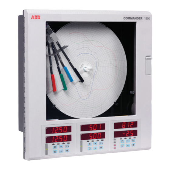
ABB COMMANDER 1900 Series Programming Manual
Circular chart recorders
Hide thumbs
Also See for COMMANDER 1900 Series:
- User manual (36 pages) ,
- Programming manual (33 pages) ,
- Operating manual (44 pages)

Related Manuals for ABB COMMANDER 1900 Series


Summary of Contents for ABB COMMANDER 1900 Series
- Page 1 Programming Guide COMMANDER 1900 Series Circular Chart Recorders Controller Versions ABB Automation...
- Page 2 St Neots, U.K. – Cert. No. Q5907 environmental applications. Stonehouse, U.K. – Cert. No. FM 21106 As a part of ABB, a world leader in process automation technology, we offer customers application expertise, service and support worldwide. EN 29001 (ISO 9001) We are committed to teamwork, high quality manufacturing, advanced technology and unrivalled service and support.
-
Page 3: Table Of Contents
CONTENTS 1 INTRODUCTION Section Page The COMMANDER 1900 series of documentation is shown in Fig. 1.1. The , including the specification Standard Manuals INTRODUCTION ............1 sheet, are supplied with all instruments. The Supplementary supplied depend on the specification of the Manuals GENERAL PROGRAMMING ........ -
Page 4: General Programming
2 GENERAL PROGRAMMING 3 BASIC CONFIGURATION LEVEL The programming procedures are used to make changes to 3.1 Set Up Input ............4 the operating parameter values and for scale adjustment – • Input types see Fig. 3.2. • Linearization • Electrical ranges •... - Page 5 OPrtOr LEVEL Operator Level bASIC CONFIG Basic Config Set Up Inputs Set Up Pen Range Set Up Chart Set Up Alarms Set Up Relay Output Set Up Digital Output Set Up Analog Output Access Page Scale Adjust Digital Inputs CONtrOL Section 3.6 Page 18 Section 3.7 Page 20 Section 3.1 Page 4...
- Page 6 …3 BASIC CONFIGURATION LEVEL 3.1 Set Up Input (Process Variable, Remote Set Point and Position Feedback) Information. • Universal inputs – mV, mA, V, THC, RTD and resistance. • Internal cold junction compensation. • Linearization – of temperature sensors to allow use of non-linearizing transmitters or any electrical input. •...
-
Page 7: Set Up Input (Process Variable, Remote Set Point And Position Feedback)
3 BASIC CONFIGURATION LEVEL… …3.1 Set Up Input Page Header – Set Up Input (Process Variable) SEt UP INPUt To advance to press the switch. Set Up Pen Range Page Select Channel SELECt Select the channel to be programmed: PV–4 PV–4 –... - Page 8 …3 BASIC CONFIGURATION LEVEL …3.1 Set Up Input rNG–HI Input Range High Set the maximum electrical input value required (in electrical units). 20 . 0 Note. The value set must be within the limits detailed in the table below. Input Type l l i tCPL l l i...
- Page 9 3 BASIC CONFIGURATION LEVEL… …3.1 Set Up Input dECPt Decimal Point Set the decimal point position required for the engineering range high and engineering 1000 both range low values. ENG–LO Engineering Range Low Set the minimum engineering (display) value required, PFb–x Note.
-
Page 10: Set Up Pen Range/Event Source
…3 BASIC CONFIGURATION LEVEL 3.2 Set Up Pen Range/Event Source Information. • Trend pens – have an independent chart range allowing a selected part of the engineering (display) range to be used for extra resolution on the chart. • Three position event pen function – can be driven by digital inputs, alarms, logic equation results, real time events (timer option), control modes, set points, ramp/soak profile segments or programs (profile option). -
Page 11: Set Up Chart
3 BASIC CONFIGURATION LEVEL… 3.3 Set Up Chart Information. • Programmable chart duration – between 1 and 167 hours or 7 and 32 days. • Chart stop function – the chart can be stopped by an alarm, digital input, logic equation result or a real time event (if timer option is fitted). - Page 12 …3 BASIC CONFIGURATION LEVEL 3.4 Set Up Alarms Information. • Four alarms per channel – identified A1 to D1 (for channel 1) up to A4 to D4 (for channel 4). • Three operator acknowledge options. • Global alarm acknowledgment – by digital input, alarm, logic equation result or real time event (if option fitted). •...
- Page 13 3 BASIC CONFIGURATION LEVEL… Hysteresis Value High Deviation Positive Trip Value Control Set Point High Deviation Negative Trip Value Process Hysteresis Variable Value Alarm On High Deviation (Positive Trip) Alarm Off Alarm On High Deviation (Negative Trip) Alarm Off Process Variable Hysteresis Value...
- Page 14 …3 BASIC CONFIGURATION LEVEL …3.4 Set Up Alarms The maximum time it takes to detect an alarm condition is present (T), in seconds, is calculated as follows: 1800 T = 10.81 + 10.1 10.1 Trip Value The time it takes for the alarm state to be cleared once the alarm condition has been removed is also equal to T.
-
Page 15: Set Up Alarms
3 BASIC CONFIGURATION LEVEL… …3.4 Set Up Alarms SEt UP Page Header – Set Up Alarms ALArMS To advance to press the switch. Set Up Relay Output Page ACKtYP Alarm Acknowledge Type LAtCH Alarms may be acknowledged while they are displayed. Select the alarm acknowledge type: NOrMAL NONE... -
Page 16: Alarm Type
…3 BASIC CONFIGURATION LEVEL …3.4 Set Up Alarms tYPE Alarm Type Select the alarm type required for the alarm selected. S–rAtE F–rAtE S–rtE – slow rate (rate of change of process variable) LO–dEV F–rtE – fast rate (rate of change of process variable) HI–dEV LO–dEV –... - Page 17 3 BASIC CONFIGURATION LEVEL… 3.5 Set Up Relay Output Information. • Relays – can be energized by alarms, logic equation results, digital inputs, control and set point modes, real time events, (timer option), totalizer wrap signal (totaliser option) and ramp/soak programs/segments (profile option). •...
-
Page 18: Set Up Relay Output
…3 BASIC CONFIGURATION LEVEL …3.5 Set Up Relay Output SEt UP Page Header – Set Up Relays rELAYS To advance to press the switch. Set Up Digital Output Page SELECt Select Relay Output rLY 1. 1 Select the output to be programmed. The selections in this frame relate to the number of fitted modules with relays and their relative module positions. - Page 19 3 BASIC CONFIGURATION LEVEL… Source Description ACFAIL Power Failure AL_ACK Alarm acknowledge – an unacknowledged process alarm condition anywhere in the unit SEG–99 Profile segment 99 SEG–0 Profile segment 0 PG-2. 1 0 Profile program 10, Controller 2 Profile (ramp/soak) control for controller 1 or 2 PG-1.
- Page 20 …3 BASIC CONFIGURATION LEVEL 3.6 Set Up Digital Output Information. • This page is not displayed if there are no digital outputs fitted. • Up to 24 digital outputs are available – depending on the module types fitted. • Digital outputs – can be energized by alarms, logic equations results, digital inputs, real time events (if timer option is fitted), control modes, set points, ramp/soak profile segments or programs (if fitted) and totalizer wrap signal (if fitted).
-
Page 21: Set Up Digital Output
3 BASIC CONFIGURATION LEVEL… …3.6 Set Up Digital Output dIGtAL Page Header – Set Up Digital Outputs OUtPtS To advance to page press the switch. Set Up Analog Output SELECt Select Digital Output OUt 1. 1 Select the output to be programmed – the selections in this frame relate to the number of fitted digital output modules and their relative module positions. - Page 22 …3 BASIC CONFIGURATION LEVEL 3.7 Set Up Analog Output Information. • Fitted analog outputs – assignable to retransmit any input (process variable, remote set point or position feedback) or provide the control output. • Selectable retransmission range – allows maximum resolution on range of interest. •...
-
Page 23: Set Up Analog Output
3 BASIC CONFIGURATION LEVEL… …3.7 Set Up Analog Output SEt UP Page Header – Set Up Analog Output ANALOG To advance to press the switch. Digital Inputs Page SELECt Select Analog Output Select the analog output position to be programmed. The selections in this frame relate to the POSN–1 number of fitted modules with analog output. -
Page 24: Digital Inputs
…3 BASIC CONFIGURATION LEVEL 3.8 Digital Inputs Information. • Up to 30 digital inputs are available – depending on the module types fitted. • Volt-free contacts or TTL levels. • Polarity – sets the logic state (unchanged or inverted) for the module position(s). Polarity Select Digital Input Logic State... -
Page 25: Access Page
3 BASIC CONFIGURATION LEVEL… 3.9 Access Page Information. • Configurable password protection – of programming levels. • Internal security link – enable/disable password protection. ACCESS Page Header – Access Page. PAGE To advance to press the switch. Scale Adjust Page t1–PAS Tune Passsword 1 (Controller 1) A tune password can be assigned to controller 1 to prevent access to its control settings. - Page 26 …3 BASIC CONFIGURATION LEVEL 3.10 Scale Adjust Information. • Analog Inputs – do not require re-calibrating when the input type or range is changed. • Span and offset adjust reset – removes any previously programmed Offset or Scale Adjustment settings. •...
-
Page 27: Scale Adjust
3 BASIC CONFIGURATION LEVEL… …3.10 Scale Adjust SCALE Page Header – Scale Adjust AdJUSt To advance to frame use the switch. BASIC CONFIGURATION LEVEL SELECt Select Process Variable/Pen Select process variable or pen required: LINCHK LINCHK – the pens automatically draw a test pattern to check pen linearity. dONE FILtEr displayed on completion... - Page 28 …3 BASIC CONFIGURATION LEVEL …3.10 Scale Adjust SELECt Calibrate Pen At 100% PEN-x SEtPEN Drives the pen automatically to the full scale position on the chart. At 100 Use the switches to set pen to 100% on the chart. SEtPEN Calibrate Pen At 0% Drives the pen automatically to the zero position on the chart.
-
Page 29: Control Configuration Level
4 CONTROL CONFIGURATION LEVEL OPrtOr LEVEL Operator Level bASIC CONFIG Basic Config CONtrL CONFIG Set Up Digital Set Points Page Valve Page Set Up Control Page Operating Page Set Up Control Config Section 4.5, Page 45 Section 4.1, Page 29 Section 4.2.3, Page 35 Section 4.3.1, Page 36 Section 4.4, Page 44... - Page 30 …4 CONTROL CONFIGURATION LEVEL Set Points ..............29 • Cascade control ..........30 • High and low set point limits ......32 • Set point tracking ........... 33 • Ratio and bias for remote/cascade set point . 33 Motorized Valve Control ......... 34 •...
- Page 31 4 CONTROL CONFIGURATION LEVEL… 4.1 Set Points Information. • Two local set points – Local and Dual. • Remote set point facility – with Ratio and Bias. • Remote set point tracking options – for bumpless Remote-to-Local set point transfers. •...
-
Page 32: Set Points
…4 CONTROL CONFIGURATION LEVEL …4.1 Set Points Information. • Cascade control – comprises two series-connected controllers (master and slave), each containing a complete measuring and controlling system operating on a single regulating device. Cascade control is only available when two control front panels are fitted (channel 1 and channel 2) and channel 2 has no Remote set point facility. -
Page 33: Cascade Control
4 CONTROL CONFIGURATION LEVEL… 4.1.2 Cascade Control (with output tracking) Controller 1 Controller 2 Master Slave Full Automatic Cascade Control Mode Auto Auto A ratio and bias can be applied to the cascade set point (derived from the master output) to give the required slave set point. P.I.D. -
Page 34: Set Points Page
…4 CONTROL CONFIGURATION LEVEL 4.1.3 Set Points Page Page Header – Set Points. POINtS To advance to press the switch. Valve Page SELECt Select Controller CtrL 2 Select the controller to be programmed (1 or 2). CtrL 1 Note. In the remaining frames press the switch to view the controller selected. - Page 35 4 CONTROL CONFIGURATION LEVEL… …4.1.3 Set Points Page REMOTE CASCADE OP trK Output Tracking Enable With Output Tracking enabled, if the slave controller is changed to local set point, the Master output tracks the local set point value of the slave. Remote (Cascade) Set Point Tracking Enable CAStrK rSPtrK...
-
Page 36: Motorized Valve Control
…4 CONTROL CONFIGURATION LEVEL 4.2 Motorized Valve Control Information. This page is not displayed if position proportioning or boundless control is not enabled on either of the controllers. • Motorized valve control with or without feedback – position-proportioning (with feedback) or boundless (without feedback). -
Page 37: Valve Page
4 CONTROL CONFIGURATION LEVEL… 4.2.3 Valve Page VALVE Page Header – Valve Page. PAGE To advance to press the switch. Set Up Control Page SELECt Select Controller CtrL 2 Select the controller to be programmed (1 or 2). CtrL 1 Note. -
Page 38: Set Up Control
…4 CONTROL CONFIGURATION LEVEL 4.3 Set Up Control Information. • Control types – Current Proportioning, Time Proportioning (and On/Off), Position-proportioning (motorized valve control with feedback), Boundless and Heat/Cool. • Programmable power-up control modes and outputs. • Reverse and direct control actions. •... -
Page 39: Set Up Control Page (Control Type)
4 CONTROL CONFIGURATION LEVEL… …4.3.1 Set Up Control Page (control type) Feedback Time Proportioning Heat Output Analog Output Process P.I.D. Variable Control Process Set Point Terms Time Proportioning Cool Output Analog Output C1900 Controller Fig. 4.6 Heat/Cool Control Schematic Diagram Feedback Process Open Relay... -
Page 40: Power Failure Mode
…4 CONTROL CONFIGURATION LEVEL 4.3.2 Set Up Control Page (power-fail mode) Information. • Programmable power-up mode. • Programmable output (or valve position) values. PFMOdE Power Failure Mode LASt Select the default power fail mode required following a power interruption or failure: LASt –... -
Page 41: Set Up Control Page
4 CONTROL CONFIGURATION LEVEL… …4.3.2 Set Up Control Page (power-fail mode) MANUAL Manual-to-Manual Power Fail Output: MAN. M AN is the control output value required when power-down state is Manual and power-up state is OP --- Manual. Set the control output value (or valve position) required following a power failure, between 0 and LASt LASt 100% in increments of 1%, or... - Page 42 …4 CONTROL CONFIGURATION LEVEL 4.3.3 Set Up Control Page (control actions and limits – non heat/cool) Information. • Two control offsets. • Programmable control actions for all outputs. • High/low output (or valve position) limits, when in auto control mode. OFFSEt Control Offset Select the offset required, 0 or 50%.
-
Page 43: Set Up Control Page
4 CONTROL CONFIGURATION LEVEL… 4.3.4 Set Up Control Page (control actions and limits – heat/cool) Information. • Independently programmable control actions for heat and cool outputs – direct or reverse. • Output limits for heat and cool outputs. ACtION Control Action (Heat) Select the action for the heat and P.I.D. - Page 44 …4 CONTROL CONFIGURATION LEVEL 4.3.5 Set Up Control Page (default control actions) Information. • Programmable default control action if input exceeds fault levels – independently programmable for all inputs (process variable, remote set point and position feedback). Examples show fault detection levels of 10% Process Variable &...
-
Page 45: Set Up Control Page
4 CONTROL CONFIGURATION LEVEL… …4.3.5 Set Up Control Page (default control actions) dFA-PV Default Action (Process Variable) dEF-OP Select the default control action required if the process variable exceeds its fault detection level (set in the page, Set Up Input BASIC CONFIGURATION LEVEL HOLd dEF–OP... -
Page 46: Set Up Operating Page
…4 CONTROL CONFIGURATION LEVEL 4.4 Set Up Operating Page Information. • Customized display of parameters in the Operating Page. • Power-fail indication – if enabled, LINE FAILEd is displayed to indicate that a power failure has occurred. • Auto/Manual switch –... -
Page 47: Set Up Digital Page
4 CONTROL CONFIGURATION LEVEL… 4.5 Set Up Digital Page Information. • Digitally selectable control modes and set point types. • Up to 3 digitally selectable local set points. • Digital signal sources – can be from external digital inputs, internal alarms, logic equations, control modes, ramp/soak events or totalizer signals. -
Page 48: Set Up Digital Inputs
4 CONTROL CONFIGURATION LEVEL 4.6 Set Up Digital Inputs Local/Remote (or Dual) Set Point Source Lr SrC Select a source to switch between Local and Remote set points. Remote/Dual Set Point 2nd-2 Active Inactive NONE Local Local Set Point Source LOC. -
Page 49: Advanced Configuration Level
5 ADVANCED CONFIGURATION LEVEL Set Up Function Keys ............................... 48 Set Up Logic ..................................49 Set Up Pen Functions ............................... 51 OPrtOr LEVEL Operator Level bASIC CONFIG Basic Config CONtrL CONFIG Control Config AdVNCd CONFIG Set Up Functions Keys Set Up Logic Set Up Pen Functions Input Assignment Advanced Config... -
Page 50: Set Up Function Keys
…5 ADVANCED CONFIGURATION LEVEL 5.1 Set Up Function Keys Information. • Programmable function key – on each faceplate. • Home function – returns the instrument display to the start of the when at the top of any page. Operating Page •... - Page 51 5 ADVANCED CONFIGURATION LEVEL… 5.2 Set Up Logic Information. • 8 logic equations. • 7 elements per equation. • OR/AND operators. • Can combine internal and external digital signals – i.e. alarms, digital inputs, other logic equation results, real time events (if timer option is fitted), control modes set point modes and profile segments and programs (if option is fitted).
-
Page 52: Set Up Logic
…5 ADVANCED CONFIGURATION LEVEL …5.2 Set Up Logic Page Header – Set Up Logic SEt UP LOGIC To advance to press the switch. Set Up Pen Functions Page SELECt Select Equation EQN1 Select equation to be constructed. EQN2 Note. In the remaining frames press the switch to view the equation selected. -
Page 53: Set Up Pen Functions
5 ADVANCED CONFIGURATION LEVEL… 5.3 Set Up Pen Functions Information. • Any fitted pen can be assigned to a trend or an event function. Page Header – Pen Functions FUNCtN To advance to frame press the switch. Advanced Configuration PEN–1 Pen 1 trENd Select pen function required:... -
Page 54: Input Assignment
…5 ADVANCED CONFIGURATION LEVEL 5.4 Input Assignment Information. • Assignment Process Variables, Remote Set Points and Position Feedbacks – can all be assigned to any analog input or maths block result (if fitted). INPUt Page Header – Input Assign ASSIGN Note. - Page 55 Main Input, Standard Input & Analog + Relay 4 Relays Module 8 Digital Inputs/Outputs Module Common Common Analog Output – Input 1 Output 1 Relay 1 Input 2 Output 2 Input 3 Output 3 Analog Input Input 4 Output 4 Relay 2 Input 5 Output 5...
- Page 56 PRODUCTS & CUSTOMER SUPPORT A Comprehensive Instrumentation Range Customer Support Analytical Instrumentation ABB Instrumentation provides a comprehensive after sales service via a Worldwide Service Organization. Contact one of • Transmitters the following offices for details on your nearest Service and...
- Page 57 The Company’s policy is one of continuous product improvement and the right is reserved to modify the information contained herein without notice. © ABB 1999 Printed in UK (11.99) ABB Instrumentation Ltd ABB Automation Inc. ABB Instrumentation SpA St. Neots...