Table of Contents
Quick Links
GE
Grid Solutions
GE Grid Solutions
650 Markland Street
Markham, Ontario
Canada L6C 0M1
Tel: +1 905 927 7070 Fax: +1 905 927 5098
Internet:
http://www.gegridsolutions.com
Transformer Protection System
Instruction Manual
745 revision: 5.20
Manual Part Number: 1601-0161-AG
GE publication code: GEK-106635Q
*1601-0161-AG*
745
I I SO9001:2000
Table of Contents

Related Manuals for GE 745


Summary of Contents for GE 745
- Page 1 Grid Solutions Transformer Protection System Instruction Manual 745 revision: 5.20 Manual Part Number: 1601-0161-AG GE publication code: GEK-106635Q GE Grid Solutions 650 Markland Street Markham, Ontario I I SO9001:2000 Canada L6C 0M1 Tel: +1 905 927 7070 Fax: +1 905 927 5098 Internet: http://www.gegridsolutions.com...
- Page 2 GE Multilin Inc. The contents of this manual are the property of GE Multilin Inc. This documentation is furnished on license and may not be reproduced in whole or in part without the permission of GE Multilin Inc. The content of this manual is for informational use only and is subject to change without notice.
-
Page 3: Table Of Contents
AC V ......................3-14 OLTAGE NPUT ........................3-14 OGIC NPUTS ........................ 3-15 ONTROL OWER ........................3-16 NALOG NPUT ......................3-16 OSITION NPUT RTD D ......................3-16 RIVER ENSOR ........................3-16 UTPUT ELAYS 745 TRANSFORMER PROTECTION SYSTEM – INSTRUCTION MANUAL TOC–I... - Page 4 ..........................4-8 VERVIEW ........................... 4-8 ARDWARE 745 S ............ 4-10 NSTALLING THE ISTA ETUP OFTWARE CONNECTING ENERVISTA 745 SETUP TO THE RELAY ............4-13 ................ 4-13 ONFIGURING SERIAL COMMUNICATIONS ................4-15 SING THE UICK ONNECT EATURE ..............4-15 ONFIGURING THERNET COMMUNICATIONS ....................
- Page 5 NALOG NPUT EVEL ......................5-95 URRENT EMAND ....................5-96 RANSFORMER VERLOAD ...................... 5-97 HANGER AILURE S5 OUTPUTS ............................5-99 ........................5-99 ESCRIPTION ......................5-99 ELAY SSIGNMENTS ™ ..................5-99 NTRODUCTION TO OGIC 745 TRANSFORMER PROTECTION SYSTEM – INSTRUCTION MANUAL TOC–III...
- Page 6 TARGET AND FLASH MESSAGES ....................6-23 ......................6-23 ARGET ESSAGES ......................6-25 TEST RRORS ........................ 6-27 LASH ESSAGES 7: COMMISSIONING GENERAL .............................. 7-1 ........................7-1 NTRODUCTION ......................7-2 ESTING HILOSOPHY ......................7-2 AFETY RECAUTIONS ........................7-2 ONVENTIONS TOC–IV 745 TRANSFORMER PROTECTION SYSTEM – INSTRUCTION MANUAL...
- Page 7 ......................A-1 EVISION ISTORY 745 M ..................A-2 HANGES TO THE ANUAL EU DECLARATION OF CONFORMITY ..................A-5 EU D ....................... A-5 ECLARATION GE DIGITAL ENERGY WARRANTY ....................A-6 ..................... A-6 ARRANTY TATEMENT 745 TRANSFORMER PROTECTION SYSTEM – INSTRUCTION MANUAL TOC–V...
- Page 8 B: INDEX TOC–VI 745 TRANSFORMER PROTECTION SYSTEM – INSTRUCTION MANUAL...
-
Page 9: Important Procedures
• Ensure that the following items are included: – Instruction manual – GE EnerVista CD (includes software and relay documentation) – Mounting screws • For product information, instruction manual updates, and the latest software updates, please visit the GE Multilin website at http://www.GEmultilin.com... - Page 10 Specifications on page 2–5. The remainder of this manual should be read and kept for reference to ensure maximum benefit from the 745 Transformer Protection System. For further information, please consult your local sales representative or the factory. Comments about new features or modifications for your specific requirements are welcome and encouraged.
-
Page 11: Using The Relay
MESSAGE UP or DOWN keys to scroll through the available sub-pages, until the desired message is reached. The process is identical for both setpoints and actual values. The following procedure illustrates the key sequence to access the Current Demand actual values. 745 TRANSFORMER PROTECTION SYSTEM – INSTRUCTION MANUAL 1–3... - Page 12 The menu path to the value shown above is indicated as A2 METERING DATA ZERO SEQUENCE CURRENT METERING W1 NEG SEQ CURRENT. Setpoints and actual values messages are referred to in this manner throughout the manual. 1–4 745 TRANSFORMER PROTECTION SYSTEM – INSTRUCTION MANUAL...
- Page 13 Pressing the MESSAGE LEFT key reverses the process described above and returns the display to the previous level. AGING FACTOR [ LIMIT Press the MESSAGE LEFT key twice to return to the S4 ELEMENTS page header. SETPOINTS S4 ELEMENTS 745 TRANSFORMER PROTECTION SYSTEM – INSTRUCTION MANUAL 1–5...
-
Page 14: Changing Setpoints
Again, continuing to press the VALUE DOWN key while at the minimum value will continue setpoint selection from the maximum value. 1–6 745 TRANSFORMER PROTECTION SYSTEM – INSTRUCTION MANUAL... -
Page 15: T Ext S Etpoints
Continue editing all the characters in the text until the string INST DIFF TRIP is entered. Note that a space is selected like a character. If a character is entered 745 TRANSFORMER PROTECTION SYSTEM – INSTRUCTION MANUAL 1–7... - Page 16 Once complete, press ENTER to remove the solid cursor and save the result. OUTPUT 3 NAME: INST DIFF TRIP 1–8 745 TRANSFORMER PROTECTION SYSTEM – INSTRUCTION MANUAL...
-
Page 17: Security
The current passcode is '0', so press the '0' numeric key. The relay will acknowledge the key press by displaying ‘*’. PLEASE ENTER CURRENT PASSCODE: Press the ENTER key. ENTER NEW PASSCODE FOR ACCESS: 745 TRANSFORMER PROTECTION SYSTEM – INSTRUCTION MANUAL 1–9... -
Page 18: S Ecurity
Enter the current passcode and press the ENTER key. This flash message indicates that the keyed in value was accepted and that passcode security is now disabled. SETPOINT ACCESS IS NOW ALLOWED 1–10 745 TRANSFORMER PROTECTION SYSTEM – INSTRUCTION MANUAL... - Page 19 Press the ENTER key and this message will flash on the display. It indicates that passcode security is now enabled. SETPOINT ACCESS IS NOW RESTRICTED After a few seconds, the original display returns. 745 TRANSFORMER PROTECTION SYSTEM – INSTRUCTION MANUAL 1–11...
- Page 20 SECURITY CHAPTER 1: GETTING STARTED 1–12 745 TRANSFORMER PROTECTION SYSTEM – INSTRUCTION MANUAL...
-
Page 21: Introduction
NEMA standards; but no such assurance is given with respect to local codes and ordinances because they vary greatly. The 745 Transformer Protection System™ is a high speed, multi-processor based, three- phase, two or three winding, transformer management relay intended for the primary protection and management of small, medium and large power transformers. -
Page 22: P Rotection F Eatures
FlexLogic™ which allows PLC style equations based on logic inputs and protection elements to be assigned to any of the 745 outputs. The 745 also includes a powerful testing and simulation feature. This allows the protection engineer the ability to test the relay operation based on captured or computer generated waveform data which can be converted to a digitized format and downloaded into the 745’s simulation buffer for “playback”. -
Page 23: Order Code
Ground differential (restricted ground fault) Current demand 2THD Total harmonic distortion level Current demand FIGURE 2–1: Single line diagram 2.1.3 Order Codes The order codes for the 745 Transformer Protection System are shown below. 745 TRANSFORMER PROTECTION SYSTEM – INSTRUCTION MANUAL 2–3... - Page 24 Analog inputs/outputs Loss of life Restricted ground fault Display/Ethernet Discontinued: Basic display Enhanced display, larger LCD, two RS485 ports Enhanced display, larger LCD, one RS485, Ethernet Harsh environment Harsh (chemical) environment conformal coating 2–4 745 TRANSFORMER PROTECTION SYSTEM – INSTRUCTION MANUAL...
-
Page 25: Specifications
Source VT ratio: ..........1 to 5000 in steps of 1 Relay input: ............60 to 120 V phase-neutral Burden:..............less than 0.025 VA at 120 V Maximum continuous input: 273 V Maximum accuracy input: 260 V (full-scale) 745 TRANSFORMER PROTECTION SYSTEM – INSTRUCTION MANUAL 2–5... -
Page 26: P Rotection E Lements
> 1.1 × kneepoint:..30 to 40 ms INSTANTANEOUS DIFFERENTIAL OVERCURRENT Pickup level:............3.00 to 20.00 × CT in steps of 0.01 Dropout level: ...........97 to 98% of pickup Level accuracy: ..........per current input 2–6 745 TRANSFORMER PROTECTION SYSTEM – INSTRUCTION MANUAL... - Page 27 Operating current pickup: 0.05 to 1.00 × CT in steps of 0.01 Operating voltage pickup: 0.10 to 0.99 × VT in steps of 0.01 Pickup level: ............45.00 to 59.99 Hz in steps of 0.01 Dropout level: ...........pickup + 0.03 Hz 745 TRANSFORMER PROTECTION SYSTEM – INSTRUCTION MANUAL 2–7...
- Page 28 Solid state output operate time: 20 to 120 ms at 1.10 × pickup Relay outputs 2 to 5 operate time: 25 to 125 ms (delay set at 0.0 s) at 1.10 × pickup 2–8 745 TRANSFORMER PROTECTION SYSTEM – INSTRUCTION MANUAL...
-
Page 29: O Utputs
5000 VA AUXILIARY 6 TO 8 RELAYS, SELF-TEST RELAY 9 Configuration:..........form-C Contact material:..........silver alloy Maximum ratings:..........300 V AC, 250 V DC, 15 A, 1500 VA Make/carry:............10 A continuous; 30 A for 0.2 s 745 TRANSFORMER PROTECTION SYSTEM – INSTRUCTION MANUAL 2–9... -
Page 30: M Iscellaneous
Event content:..........see Types and causes of events on page 6–19 OPERATING ENVIRONMENT Operating temperature: ......–40°C to +60°C Storage temperature:........–40°C to +80°C ambient Humidity:............up to 90% non-condensing Altitude: ...............2000 m Pollution degree:..........II CASE Drawout:.............Fully drawout unit (automatic CT shorts) 2–10 745 TRANSFORMER PROTECTION SYSTEM – INSTRUCTION MANUAL... - Page 31 Thermal:..............operational test at ambient then increasing to 60°C Dielectric strength: ........(order code ’LO’) 550 VAC for 1 second (order code ’HI’) 2200 VAC for 1 second TYPE WITHSTAND TESTS The following table lists the 745 type tests: Standard Test Name Level...
- Page 32 SPECIFICATIONS CHAPTER 2: OVERVIEW Specifications subject to change without notice. Note NOTE 2–12 745 TRANSFORMER PROTECTION SYSTEM – INSTRUCTION MANUAL...
-
Page 33: Drawout Case
3.1.1 Case Description The 745 is packaged with a drawout relay and a companion case. The case provides mechanical protection for the drawout portion, and is used to make permanent electrical connections to external equipment. Where required, case connectors are fitted with mechanisms, such as automatic CT shorting, to allow the safe removal of the relay from an energized panel. -
Page 34: Panel Cutout
3.1.3 Case Mounting Before mounting the 745 unit in the supporting panel, remove the relay portion from its case, as described in the next section. From the front of the panel, slide the empty case into the cutout. To ensure the front bezel sits flush with the panel, apply pressure to the bezel’s front while bending the retaining tabs 90°. - Page 35 Release the locking latch, located below the locking handle, by pressing upward on the latch with the tip of a screwdriver. FIGURE 3–5: Press latch to disengage handle 745 TRANSFORMER PROTECTION SYSTEM – INSTRUCTION MANUAL 3–3...
- Page 36 Hold the unit immediately in front of the case and align the rolling guide pins (near the hinges of the locking handle) to the guide slots on either side of the case. 3–4 745 TRANSFORMER PROTECTION SYSTEM – INSTRUCTION MANUAL...
- Page 37 If access to the front panel controls must be restricted, a separate seal can be installed on the outside of the cover to prevent it from being opened. FIGURE 3–8: Drawout unit seal 745 TRANSFORMER PROTECTION SYSTEM – INSTRUCTION MANUAL 3–5...
-
Page 38: E Thernet Connection
CHAPTER 3: INSTALLATION 3.1.5 Ethernet connection If using the 745 with the Ethernet 10Base-T option, ensure that the network cable is disconnected from the rear RJ45 connector before removing the unit from the case. This prevents any damage to the connector. -
Page 39: Typical Wiring
3.2.1 Description The 745 contains numerous built-in features that allow for a broad range of applications. As such, it is not possible to present connections for all possible schemes. The information in this section covers the important aspects of interconnections, in the general areas of instrument transformer inputs, other inputs, outputs, communications, and grounding. - Page 40 Phase A: winding 1 CT Logic input 2 (+) Phase B: winding 1 CT Logic input 3 (+) Phase C: winding 1 CT Logic input 4 (+) Phase A: winding 2 CT 3–8 745 TRANSFORMER PROTECTION SYSTEM – INSTRUCTION MANUAL...
- Page 41 Ground: winding 1/2 CT Logic power out (+) Control power (–) Logic power out (–) Control power (+) symbol indicates the high side of CT and VT terminals Note NOTE 745 TRANSFORMER PROTECTION SYSTEM – INSTRUCTION MANUAL 3–9...
-
Page 42: W Iring D Iagrams
In addition, depending on which winding the VT is on, the power NOTE flows and vars displayed may be opposite in direction to the actual system flow; e.g. in the 3–10 745 TRANSFORMER PROTECTION SYSTEM – INSTRUCTION MANUAL... - Page 43 VT is connected to, the power may be negative when the generator is producing positive MW. This can be corrected by reversing the voltage input into C11 and C12. FIGURE 3–12: Typical wiring for three-winding transformer 745 TRANSFORMER PROTECTION SYSTEM – INSTRUCTION MANUAL 3–11...
-
Page 44: Input
1 to 50000 A primaries may be used. The 745 Relay has inputs for either two or three transformer windings (specified at the time of ordering) and for two ground current inputs, G1/2 and G2/3. Refer to the wiring diagrams below for details. - Page 45 Winding 2 Delta Delta Winding 1 Winding 3 Delta Delta Winding 2 Winding 3 Delta Delta Winding 2 Winding 1 Delta Delta Winding 3 Winding 1 Delta Delta Winding 3 Winding 2 745 TRANSFORMER PROTECTION SYSTEM – INSTRUCTION MANUAL 3–13...
-
Page 46: Ac Voltage Input
3.2.6 AC Voltage Input The 745 has one voltage divider type input for AC voltages. There are no internal fuses or ground connections. Voltage transformers up to a maximum 5000:1 ratio may be used. The nominal secondary voltage must be in the 60 to 120 V range. -
Page 47: Control Power
WARNING FIGURE 3–15: Control power connection Extensive filtering and transient protection are built into the 745 to ensure proper operation in harsh industrial environments. Transient energy must be conducted back to the source through the filter ground terminal. A separate safety ground terminal is provided for dielectric strength (hi-pot) testing. -
Page 48: Analog Input
In the two-wire connection scheme, the connection from terminal B11 to B12 is made at the terminal block on the rear of the 745. This connection must not be omitted. The two- wire connection scheme does not compensate for the resistance of the wiring between the 745 and the RTD. -
Page 49: Output
3.2.14 Analog Outputs The 745 provides 7 analog output channels whose full scale range can be set to one of the following ranges: 0 to 1 mA; 0 to 5 mA; 0 to 10 mA; 0 to 20 mA; and 4 to 20 mA. Each analog output channel can be programmed to represent one of the parameters measured by the relay. - Page 50 An isolated power supply with an optocoupled data interface also acts to reduce noise coupling. To ensure maximum reliability, all equipment should have similar transient protection devices installed. FIGURE 3–17: RS485 wiring 3–18 745 TRANSFORMER PROTECTION SYSTEM – INSTRUCTION MANUAL...
-
Page 51: Program Port
A 9 pin RS232C serial port is located on the front panel for programming through a PC. This port uses the same Modbus protocol as the two rear ports. The EnerVista 745 Setup software required to use this interface is included with the relay. Cabling for the RS232 port is shown below for both 9 pin and 25 pin connectors. -
Page 52: Irig-B
FIGURE 3–20: IRIG-B function 3.2.18 Dielectric Strength Dielectric strength test was performed on the 745 relay at the manufacturer. It is not necessary to perform this test again at the customer site. However, if you wish to perform this test, follow instructions outlined in Dielectric Strength Testing on page 7–6. - Page 53 No special ventilation requirements need to be observed during the installation of the Note unit. The unit does not have to be cleaned. NOTE Hazard may result if the product is not used for its intended purpose. WARNING 745 TRANSFORMER PROTECTION SYSTEM – INSTRUCTION MANUAL 3–21...
- Page 54 TYPICAL WIRING CHAPTER 3: INSTALLATION 3–22 745 TRANSFORMER PROTECTION SYSTEM – INSTRUCTION MANUAL...
-
Page 55: Hardware Interface
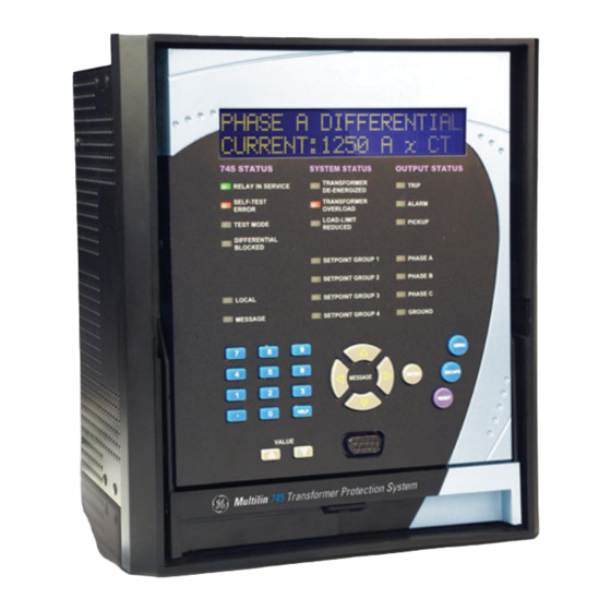
The RS232 program port is also provided for connection with a computer running the EnerVista 745 Setup software. FIGURE 4–1: 745 front panel view 745 TRANSFORMER PROTECTION SYSTEM – INSTRUCTION MANUAL 4–1... -
Page 56: D Isplay
• TEST MODE: The Test Mode LED indicator is on when any of the 745 testing features has been enabled. The indicator is on if any of the following conditions are met: –... - Page 57 The indicator is on if the harmonic inhibit element is blocking any phase (see Harmonic inhibit on page 5–52). • LOCAL: The Local LED indicator is on when the 745 is in local mode, i.e. the front panel RESET key is operational. •...
-
Page 58: Program Port
4.1.5 Program Port Use the front panel program port for RS232 communications with the 745. As described in RS232 Front Panel Program Port on page 3–19, all that is required is a connection between the relay and a computer running EnerVista 745 Setup. For continuous monitoring of multiple relays, use the COM1 RS485/RS422 port or the COM2 RS485 port. -
Page 59: S Etpoint E Ntry
Flash Memory, as a new setpoint. INPUT 1 NAME: Tx. Monitor The 745 does not have '+' or '–' keys. Negative numbers may be entered in one of two manners. – Immediately pressing one of the VALUE keys causes the setpoint to scroll through its range including any negative numbers. - Page 60 The following procedure may be used to access and alter setpoints. This specific example refers to entering a valid passcode to allow access to setpoints if the passcode was “745”. Press the MENU key to access the header of each menu, which will be displayed in the following sequence: ...
- Page 61 PREFERENCES DEFAULT MESSAGE CYCLE TIME factory default flash message time is 4 seconds. For additional information and a complete list of flash messages, refer to Flash Messages on page 6–27. 745 TRANSFORMER PROTECTION SYSTEM – INSTRUCTION MANUAL 4–7...
-
Page 62: Enervista Software Interface
It can be used while disconnected (i.e. off-line) or connected (i.e. on-line) to a 745 device. In off-line mode, settings files can be created for eventual downloading to the device. - Page 63 CHAPTER 4: INTERFACES ENERVISTA SOFTWARE INTERFACE FIGURE 4–2: Communications using the front RS232 port FIGURE 4–3: Communications using rear RS485 port 745 TRANSFORMER PROTECTION SYSTEM – INSTRUCTION MANUAL 4–9...
- Page 64 FIGURE 4–4: Communications using rear Ethernet port 4.2.3 Installing the EnerVista 745 Setup Software The following minimum requirements must be met for the EnerVista 745 Setup software to operate on your computer.) • Pentium class or higher processor (Pentium II 400 MHz or better recommended) •...
- Page 65 Select the Web option to ensure the most recent software release, or select CD if you do not have a web connection, then Click the Add Now button to list software items for the 745. 745 TRANSFORMER PROTECTION SYSTEM – INSTRUCTION MANUAL...
- Page 66 EnerVista 745 Setup software to the Windows start menu. Click Finish to end the installation. The 745 device will be added to the list of installed IEDs in the EnerVista Launchpad window, as shown below. 4–12...
-
Page 67: Connecting Enervista 745 Setup To The Relay
“Transformer Station 1” as the site name. Click the OK button when complete. The new site will appear in the upper-left list in the EnerVista 745 Setup window. Click the Add Device button to define the new device. - Page 68 9600, with slave address of 1, no parity, 8 bits, and 1 stop bit. These values cannot be changed. Click the Read Order Code button to connect to the 745 device and upload the order code.
-
Page 69: C Onnect F Eature
As indicated by the window, the quick connect feature quickly connects the EnerVista 745 Setup software to a 745 front port with the following settings: 9600 baud, no parity, 8 bits, 1 stop bit. Select the PC communications port connected to the relay and press the Connect button. - Page 70 “Transformer Station 1” as the site name. Click the OK button when complete. The new site will appear in the upper-left list in the EnerVista 745 Setup window. Click the Add Device button to define the new device.
-
Page 71: Relay
CHAPTER 4: INTERFACES CONNECTING ENERVISTA 745 SETUP TO THE RELAY The 745 Site Device has now been configured for Ethernet communications. Proceed to the following section to begin communications. 4.3.4 Connecting to the Relay Now that the communications parameters have been properly configured, the user can easily connect to the relay. - Page 72 Other setpoint and commands windows can be displayed and edited in a similar manner. Actual values windows are also available for display. These windows can be locked, arranged, and resized at will. Refer to the EnerVista 745 Setup help file for additional information about the using the Note software.
-
Page 73: Working With Setpoints And Setpoint Files
Working with Setpoints and Setpoint Files 4.4.1 Engaging a Device The EnerVista 745 Setup software may be used in on-line mode (relay connected) to directly communicate with a 745 relay. Communicating relays are organized and grouped by communication interfaces and into sites. - Page 74 For setpoints requiring an alphanumeric text string (e.g. message scratchpad messages), Enter the value directly within the setpoint value box. In any settings window, click on Save to save the values into the 745. Click Yes to accept any changes.
-
Page 75: File
Opening any EnerVista 745 Setup file will automatically launch the application or provide focus to the already opened application. If the file is a settings file (has a ‘745’ extension) which had been removed from the Settings List tree menu, it will be added back to the Settings List tree. - Page 76 4.4.4.3 Adding Setpoints Files to the Environment The EnerVista 745 Setup software provides the capability to review and manage a large group of setpoint files. Use the following procedure to add a new or existing file to the list.
- Page 77 4.4.4.5 Upgrading Setpoint Files to a New Revision It is often necessary to upgrade the revision code for a previously saved setpoint file after the 745 firmware has been upgraded (for example, this is required for firmware upgrades). This is illustrated in the following procedure.
- Page 78 Select the Actual > Product Info menu item and record the Software Revision identifier of the relay firmware as shown below. Load the setpoint file to be upgraded into the EnerVista 745 Setup environment as described in Adding Setpoints Files to the Environment on page 4–22.
- Page 79 WORKING WITH SETPOINTS AND SETPOINT FILES 4.4.4.6 Printing Setpoints and Actual Values The EnerVista 745 Setup software allows the user to print partial or complete lists of setpoints and actual values. Use the following procedure to print a list of setpoints: ...
- Page 80 4–23 for instructions on changing the revision number of a setpoint file. The following procedure illustrates how to load setpoints from a file. Before loading a setpoints file, it must first be added to the EnerVista 745 Setup environment as described in Adding Setpoints Files to the Environment on page 4–22.
-
Page 81: Upgrading Relay Firmware
4.5.2 Saving Setpoints to a File Before upgrading firmware, it is very important to save the current 745 settings to a file on your PC. After the firmware has been upgraded, it will be necessary to load this file back into the 745. - Page 82 The EnerVista 745 Setup software now prepares the 745 to receive the new firmware file. The 745 will display a message indicating that it is in Upload Mode. While the file is being loaded into the 745, a status box appears showing how much of the new firmware file has been transferred and how much is remaining, as well as the upgrade status.
- Page 83 Modbus addresses have changed with the upgraded firmware. This message does not signal any problems when appearing after firmware upgrades. 745 TRANSFORMER PROTECTION SYSTEM – INSTRUCTION MANUAL 4–29...
-
Page 84: Advanced Enervista 745 Setup Features
Waveform Capture (trace memory) The EnerVista 745 Setup software can be used to capture waveforms (or view trace memory) from the 745 relay at the instance of a trip. A maximum of 32 waveforms can be buffered (stored) with the buffer/cycle trade-off. - Page 85 CHAPTER 4: INTERFACES ADVANCED ENERVISTA 745 SETUP FEATURES The waveform file numbering starts with the number zero in the 745; therefore, the maximum trigger number will always be one less then the total number triggers available. Click on the Save to File button to save the selected waveform to the local PC.
- Page 86 Several parameters can be trended and graphed at sampling periods ranging from 1 second up to 1 hour. The parameters which can be trended by the EnerVista 745 Setup software are: 4–32 745 TRANSFORMER PROTECTION SYSTEM – INSTRUCTION MANUAL...
- Page 87 Aging factor – Tap changer position With EnerVista 745 Setup running and communications established, select the Actual Values > Trending menu item to open the trending window. To prepare for new trending, select Stop to stop the data logger and Reset to clear the screen.
- Page 88 Press “Run” to start the data logger. If the Log Samples to File item is selected, the EnerVista 745 Setup software will begin collecting data at the selected sampling rate and will display it on the screen.
- Page 89 4.6.4 Event Recorder The 745 event recorder can be viewed through the EnerVista 745 Setup software. The event recorder stores transformer and system information each time an event occurs. A maximum of 256 events can be stored, where E256 is the most recent event and E001 is the oldest event.
- Page 90 Change the event number on the Select Events box. 4.6.5 Modbus User Map The EnerVista 745 Setup software provides a means to program the 745 user map (Modbus addresses 0180h to 01F7h). Refer to GE publication GEK-106636B: 745 Communications Guide for additional information on the user map.
-
Page 91: Alues
• The status of the output relays. • Any self-test errors. Metering data: • Instantaneous current measurements including phase, neutral, and ground currents for each winding, along with differential, restraint, positive-sequence, negative-sequence, zero-sequence, and ground restraint currents. 745 TRANSFORMER PROTECTION SYSTEM – INSTRUCTION MANUAL 4–37... - Page 92 Each group will be opened on a separate tab. The windows can be re- arranged to maximize data viewing as shown in the following figure (showing actual demand, harmonic contents, and current values tiled in the same window): 4–38 745 TRANSFORMER PROTECTION SYSTEM – INSTRUCTION MANUAL...
- Page 93 CHAPTER 4: INTERFACES ADVANCED ENERVISTA 745 SETUP FEATURES Figure 4-4: Actual values display 745 TRANSFORMER PROTECTION SYSTEM – INSTRUCTION MANUAL 4–39...
-
Page 94: Using Enervista Viewpoint With The 745
Click the OK button when complete. The new site will appear in the upper-left list in the EnerVista 745 Setup window. Click the Add Device button to define the new device. - Page 95 745. See EnerVista Software Interface on page 4–8 for details. Figure 4-6: Device setup screen (example) Click the Read Order Code button to connect to the 745 device and upload the order code. If a communications error occurs, ensure that communications values entered in the previous step correspond to the relay setting values.
- Page 96 USING ENERVISTA VIEWPOINT WITH THE 745 CHAPTER 4: INTERFACES Click the Dashboard button below the 745 icon to view the device information. We have now successfully accessed our 745 through EnerVista Viewpoint. FIGURE 4–8: EnerVista plug and play screens (example) For additional information on EnerVista viewpoint, please visit the EnerVista website at http://www.enervista.com.
-
Page 97: Overview
The setpoints have been grouped into a number of pages as shown below. If using the EnerVista 745 Setup software and not connected to a relay, you may have to select the File > Properties menu item and set the correct options for your relay. - Page 98 SETPOINT GROUP [ See page 5–47 S4 ELEMENTS DIFFERENTIAL [ See page 5–48 MESSAGE INST See page 5–57 MESSAGE DIFFERENTIAL PHASE OC See page 5–58 MESSAGE 5–2 745 TRANSFORMER PROTECTION SYSTEM – INSTRUCTION MANUAL...
- Page 99 END OF PAGE S5 MESSAGE SETPOINTS [] OUTPUT RELAYS [] See page 5–107 S6 TESTING ANALOG OUTPUTS [] MESSAGE See page 5–108 SIMULATION See page 5–108 MESSAGE 745 TRANSFORMER PROTECTION SYSTEM – INSTRUCTION MANUAL 5–3...
-
Page 100: S Etpoint Entry
There are many 745 setpoints that must be entered for the relay to function correctly. In order to safeguard against installation when these setpoints have not been entered, the 745 does not allow signaling of any output relay. In addition, the In Service LED is off and the Self-Test Error LED on until the... - Page 101 Passcode protection may also be enabled. When enabled, the 745 requests a numeric passcode before any setpoint can be entered. As an additional safety measure, a minor self-test error is generated when the passcode is entered incorrectly three times in a row.
-
Page 102: Auto-Configuration
CTs or tapped relay windings and compensating CT connections at the transformer. The 745 simplifies CT configuration issues by having all CTs connected Wye (polarity markings pointing away from the transformer). All phase angle and magnitude corrections, as well as zero-sequence current compensation, are performed automatically based upon user entered setpoints. - Page 103 In this case, the mismatch factor is 1428.6 / 1500 = 0.952. The 745 allows monitoring of the tap changer position via the tap position input. With this input, the 745 dynamically adjusts the CT ratio mismatch factor based on the actual transformer voltage ratio set by the tap changer.
- Page 104 The “zero position” terminal and the “wiper” terminal of the tap position circuit are connected to the positive and negative 745 tap position terminals. Polarity is not consequential. The following setpoints configure the 745 to determine tap position. In the...
- Page 105 The example below shows why this happens, using a transformer described in IEC nomenclature as “Yd1” or in GE Multilin nomenclature as “Y/d30.” FIGURE 5–2: Example transformer The above figure shows the physical connections within the transformer that produce a phase angle in the delta winding that lags the respective wye winding by 30°.
- Page 106 Note that the delta winding currents leads the wye winding currents by 30°, (which is a type Yd11 in IEC nomenclature and a type Y/d330 in GE Multilin nomenclature) which is in disagreement with the transformer nameplate. This is because the physical connections and hence the equations used to calculate current for the delta winding have not changed.
- Page 107 Traditionally, this problem is solved by connecting the CTs on the wye side of the transformer (winding 1) in a delta arrangement. This compensates for the phase angle lag introduced in the delta side (winding 2). The 745 performs this phase angle correction internally based on the following setpoint. to “Y/d30°”. S2 SYSTEM SETUP...
- Page 108 AUTO-CONFIGURATION CHAPTER 5: SETPOINTS corrected and void of zero-sequence current. Because the 745 software mimics the CT delta connection, the zero-sequence current is automatically removed from all Wye or zig-zag winding currents of transformers having at least one delta winding.
- Page 109 0° DELTA 0° (gnd 2/3) (gnd 2/3) 180° lag 240° lag D/d300° DELTA 300° D/y30° DELTA 0° (gnd 1/2) (gnd 1/2) DELTA 0° 330° (gnd 2/3) (gnd 2/3) 300° lag 30° lag 745 TRANSFORMER PROTECTION SYSTEM – INSTRUCTION MANUAL 5–13...
- Page 110 (gnd 1/2) ZIG-ZAG 0° ZIG-ZAG 0° (gnd 2/3) (gnd 2/3) 180° lag 240° lag D/z300° DELTA 300° 3W External 0° (gnd 1/2) Correction ZIG-ZAG 0° 0° (gnd 2/3) 0° 300° lag 0° 0° 5–14 745 TRANSFORMER PROTECTION SYSTEM – INSTRUCTION MANUAL...
- Page 111 180° lag 180° lag DELTA 0° DELTA 0° 210° lag 330° lag Y/d30°/y0° 30° lag Y/d30°/y180° 30° lag DELTA 0° DELTA 0° 30° lag 30° lag 30° lag 210° lag 0° 180° lag 745 TRANSFORMER PROTECTION SYSTEM – INSTRUCTION MANUAL 5–15...
- Page 112 DELTA 0° 30° lag 150° lag Y/d150°/ 150° lag Y/d150°/ 150° lag d210° d330° DELTA 0° DELTA 0° 150° lag 150° lag DELTA 300° lag DELTA 180° lag 210° lag 330° lag 5–16 745 TRANSFORMER PROTECTION SYSTEM – INSTRUCTION MANUAL...
- Page 113 330° lag 150° lag 0° 180° lag Y/d330°/d30° 330° lag Y/d330°/ 330° lag d150° DELTA 0° DELTA 0° 330° lag 330° lag DELTA 300° lag DELTA 180° lag 30° lag 150° lag 745 TRANSFORMER PROTECTION SYSTEM – INSTRUCTION MANUAL 5–17...
- Page 114 300° lag 0° 0° DELTA 0° DELTA 0° 240° lag 300° lag D/d0°/y30° DELTA 0° D/d0°/y150° DELTA 0° DELTA 0° DELTA 0° 0° 0° 330° lag 210° lag 30° lag 150° lag 5–18 745 TRANSFORMER PROTECTION SYSTEM – INSTRUCTION MANUAL...
- Page 115 120° lag 210° lag 0° D/d120°/ DELTA 120° lag D/d120°/ DELTA 120° lag d120° d180° DELTA 0° DELTA 0° 120° lag 120° lag DELTA 0° DELTA 300° lag 120° lag 180° lag 745 TRANSFORMER PROTECTION SYSTEM – INSTRUCTION MANUAL 5–19...
- Page 116 210° lag 30° lag 150° lag 330° lag D/d240°/d0° DELTA 240° lag D/d240°/d60° DELTA 240° lag DELTA 0° DELTA 0° 240° lag 240° lag DELTA 240° lag DELTA 180° lag 0° 60° lag 5–20 745 TRANSFORMER PROTECTION SYSTEM – INSTRUCTION MANUAL...
- Page 117 30° lag DELTA 120° lag 330° lag 240° lag 30° lag D/y30°/y210° DELTA 0° D/y150°/d0° DELTA 0° 330° lag 210° lag 30° lag 150° lag 150° lag DELTA 0° 210° lag 0° 745 TRANSFORMER PROTECTION SYSTEM – INSTRUCTION MANUAL 5–21...
- Page 118 300° lag DELTA 120° lag 60° lag 240° lag D/y210°/y30° DELTA 0° D/y210°/ DELTA 0° y210° 150° lag 150° lag 210° lag 210° lag 330° lag 150° lag 30° lag 210° lag 5–22 745 TRANSFORMER PROTECTION SYSTEM – INSTRUCTION MANUAL...
- Page 119 30° lag 30° lag 330° lag 330° lag 210° lag 30° lag 150° lag 330° lag Y/z30°/z30° 30° lag Y/y0°/y0° 0° ZIG-ZAG 0° 0° 30° lag 0° ZIG-ZAG 0° 0° 30° lag 0° 745 TRANSFORMER PROTECTION SYSTEM – INSTRUCTION MANUAL 5–23...
- Page 120 = (B – A) / 300° lag a = –B b = –C c = –A 330° lag a = (A – B) / b = (B – C) / c = (C – A) / 5–24 745 TRANSFORMER PROTECTION SYSTEM – INSTRUCTION MANUAL...
- Page 121 After installing the setpoint access jumper, a passcode must be entered (if the passcode security feature is enabled) before setpoints can be changed. When the 745 is shipped from the factory, the passcode is defaulted to 0. When the passcode is 0, the passcode security feature is disabled and only the setpoint access jumper is required for changing setpoints from the front panel.
- Page 122 • DEFAULT MESSAGE TIMEOUT: After this period of time of no activity on the keys, the 745 automatically begins to display the programmed set of default messages programmed in S1 745 SETUP DEFAULT MESSAGES ...
- Page 123 Up to 32 relays can be daisy-chained and connected to a computer or a programmable controller, using either the two-wire RS485 or the four-wire RS422 serial communication port at the rear of the 745. Before using communications, each relay must be programmed with a unique address and a common baud rate.
- Page 124 • DATA LINK CONFIRM TIMEOUT: Selects a desired timeout. If no confirmation response is received within this time, the 745 will re-send the frame if retries are still available. • DATA LINK CONFIRM RETRIES: Select the maximum number of retries that will be issued for a given data link frame.
- Page 125 Resetting can be performed in any of the following ways: via RESET on the front panel while the 745 is in local mode (i.e. the Local LED indicator is on); via a logic input; via any of the communication ports.
- Page 126 PRESS [ENTER] TO REMOVE MESSAGE Press ENTER while this message is being displayed. The message is now removed from the default message list and the messages that follow are moved up to fill the gap. 5–30 745 TRANSFORMER PROTECTION SYSTEM – INSTRUCTION MANUAL...
- Page 127 To safeguard against the installation of a relay whose setpoints have not been entered, the 745 will not allow signaling of any output relay, will have the In Service LED off and the Self- Test Error LED on, until the 745 is set to “Programmed”. The setpoint is defaulted to “Not Programmed”...
- Page 128 ) and the new option(s) to be added. The factory will supply a passcode that may be used to add the new options to the 745. Before entering the passcode and performing the upgrade, it is important to set the ENABLE setpoints correctly (see descriptions below).
- Page 129 MESSAGE Enabled Range: Enabled, Disabled OFF EVENT: MESSAGE Enabled Range: Enabled, Disabled ON EVENT: MESSAGE Enabled These setpoints allow the user to configure the event recorder by enabling/disabling the event types indicated. 745 TRANSFORMER PROTECTION SYSTEM – INSTRUCTION MANUAL 5–33...
- Page 130 OF LIFE: 0 x 10h To provide accurate and effective transformer protection, the parameters of both the transformer and the system configuration must be supplied to the 745 relay. • NOMINAL FREQUENCY: Enter the nominal frequency of the power system. This setpoint is used to determine the sampling rate in the absence of a measurable frequency.
- Page 131 With this correction, the 745 will properly compare line to neutral currents on all sides of the power transformer. For example, for a two-winding delta/wye power transformer with wye-connected current...
- Page 132 Leave ground CT selection at default value of "None" if no CT is needed on the required winding. The ground input selection settings will be defaulted to "None" when an upgrade settings file is uploaded. 5–36 745 TRANSFORMER PROTECTION SYSTEM – INSTRUCTION MANUAL...
- Page 133 MESSAGE PER TAP: 33 Ω This section contains the settings to configure the tap position input. The 745 accepts a resistive input from the tap changer control circuitry, which is used in the 745 to dynamically correct for CT ratio mismatch based on the dynamically changing voltage ratio of the transformer.
- Page 134 MESSAGE NUMBER: 2nd The 745 calculates the individual harmonics in each of the phase current inputs up to the harmonic. With this information, it calculates an estimate of the effect of non- sinusoidal load currents on the transformer rated full load current. These calculations are based on ANSI/IEEE Standard C57.110-1986, and require information that is often only...
- Page 135 VT RATIO: MESSAGE 1000:1 The 745 provides a voltage input for the purposes of energization detection (for the energization inhibit feature of the percent differential element), overexcitation protection (the volts-per-hertz 1 and 2 functions), and frequency protection (the underfrequency, frequency decay, and overfrequency functions). Note that the frequency elements will use the winding 1 phase A current input if voltage is not available.
- Page 136 CHAPTER 5: SETPOINTS • AMBIENT RTD TYPE: The 745 provides an RTD input for monitoring the ambient temperature. The three RTD types which may be used are 100 Ω platinum, and 100/ 120 Ω nickel, the characteristics of which are as follows: Table 5–3: RTD resistance vs.
- Page 137 0 to 65000 in steps of 1 ANALOG INPUT MAXIMUM MESSAGE VALUE: 1000 μA The 745 provides a general purpose DC current input for use in monitoring any external parameter. Any standard transducer output may be connected to the analog input for monitoring. •...
- Page 138 “Block Interval” or “Rolling Demand”. Enter the time period over which TYPE the current demand calculation is performed. TIME INTERVAL is only displayed when “Block Interval” or “Rolling Demand” is selected Note for the CURRENT DEMAND METER TYPE. NOTE 5–42 745 TRANSFORMER PROTECTION SYSTEM – INSTRUCTION MANUAL...
- Page 139 MAX: 1000 A There are seven analog outputs on the 745 relay which are selected to provide a full-scale output range of one of 0 to 1 mA, 0 to 5 mA, 4 to 20 mA, 0 to 20 mA or 0 to 10 mA. Each channel can be programmed to monitor any measured parameter.
- Page 140 INPUT 1(16) ASSERTED STATE: Select “Closed” as when connected to a normally open contact (where the signaling state is closed). Select “Open” when connected to a normally closed contact (where the signaling state is open). 5–44 745 TRANSFORMER PROTECTION SYSTEM – INSTRUCTION MANUAL...
- Page 141 ENTER to store and advance to the next character position. • INPUT 1(16) PROGRAMMED STATE: Select “Asserted” to place the virtual input into the signaling state; likewise, select “Not Asserted” to place it into the non-signaling state. 745 TRANSFORMER PROTECTION SYSTEM – INSTRUCTION MANUAL 5–45...
- Page 142 Selecting a logic or virtual input allows blocking the element based on a decision external to the 745. Selecting an output relay or virtual output allows blocking the element based on conditions detected by the 745 and the combination of logic programmed in the associated FlexLogic™...
- Page 143 ACTIVE SETPOINT GROUP: Select the number of the whose settings SETPOINT GROUP are to be active in the protection scheme. This selection will be overridden if a higher number setpoint group is activated using logic inputs. 745 TRANSFORMER PROTECTION SYSTEM – INSTRUCTION MANUAL 5–47...
- Page 144 See page 5–56 MESSAGE INHIBIT This section contains the settings to configure the percent differential element, including all associated harmonic inhibit features. The 745 provides three independent harmonic inhibit features: , which implements an inhibit scheme based on 2nd or HARMONIC INHIBIT 2nd + 5th harmonic which is ‘in-circuit’...
- Page 145 CTs during external faults. These unbalances arise as a result of the following factors: • CT ratio mismatch (not a factor, since the 745 automatically corrects for this mismatch) • Onload tap changers which result in dynamically changing CT mismatch •...
- Page 146 This slope is set to ensure sensitivity to internal faults at normal operating current levels. The criteria for setting this slope are: 5–50 745 TRANSFORMER PROTECTION SYSTEM – INSTRUCTION MANUAL...
- Page 147 The source is connected to one winding only. Therefore, the value cannot be greater than 100%. To PERCENT DIFFERENTIAL SLOPE 2 increase dependability, the Slope 2 settings should be less than 98% FIGURE 5–9: Percent differential scheme logic 745 TRANSFORMER PROTECTION SYSTEM – INSTRUCTION MANUAL 5–51...
- Page 148 HARMONIC INHIBIT LEVEL: Enter the level of harmonic current (2 or 2 ) above which the percent differential element will be inhibited from operating. For most applications, this level should be set to “20%”. 5–52 745 TRANSFORMER PROTECTION SYSTEM – INSTRUCTION MANUAL...
- Page 149 PARALL XFMR BRKR CLS MESSAGE SIGNAL: Disabled Over and above the standard harmonic inhibit feature programmed above, the 745 contains a harmonic inhibit feature which is in service only during energization and/or sympathetic inrush. De-energization and energization of the transformer is detected by any of the following three methods: 745 TRANSFORMER PROTECTION SYSTEM –...
- Page 150 (any energization sensing enabled). • ENERGIZATION SENSING BY VOLTAGE: Select “Enabled” to detect de-energization by the level of the voltage dropping below the minimum energization voltage. This 5–54 745 TRANSFORMER PROTECTION SYSTEM – INSTRUCTION MANUAL...
- Page 151 PARALL XFMR BRKR CLS SIGNAL: Select any logic input which, when asserted, will indicate to the 745 the onset of sympathetic inrush. The selected logic input should be connected to the close command going to the parallel transformer switching device.
- Page 152 5 harmonic exceeds the level setting. • HARMONIC AVERAGING: Select “Enabled” to use the three-phase average of the 5th harmonic current against the harmonic inhibit setting. 5–56 745 TRANSFORMER PROTECTION SYSTEM – INSTRUCTION MANUAL...
- Page 153 • INST DIFFERENTIAL PICKUP: Enter the level of differential current (in units of relay nominal current) above which the instantaneous differential element will pickup and operate. 745 TRANSFORMER PROTECTION SYSTEM – INSTRUCTION MANUAL 5–57...
- Page 154 W1 PHASE See page 5–65 MESSAGE INST OC 2 W2 PHASE MESSAGE See page 5–65 INST OC 2 W3 PHASE MESSAGE See page 5–65 INST OC 2 5–58 745 TRANSFORMER PROTECTION SYSTEM – INSTRUCTION MANUAL...
- Page 155 • IEC curves: IEC curves A, B, and C (BS142); IEC short inverse • GE type IAC curves: IAC extremely inverse, IAC very inverse, IAC inverse, and IAC short inverse • Other curves: FlexCurves™ A, B, and C; definite time curve...
- Page 156 0.511 0.493 5.404 3.030 1.910 1.527 1.329 1.208 1.126 1.066 1.021 0.986 8.106 4.544 2.866 2.291 1.994 1.812 1.689 1.600 1.532 1.479 10.807 6.059 3.821 3.054 2.659 2.416 2.252 2.133 2.043 1.972 5–60 745 TRANSFORMER PROTECTION SYSTEM – INSTRUCTION MANUAL...
- Page 157 5.333 3.333 2.286 1.667 1.270 1.000 0.808 IEC short time 0.05 0.153 0.089 0.056 0.044 0.038 0.034 0.031 0.029 0.027 0.026 0.10 0.306 0.178 0.111 0.088 0.075 0.067 0.062 0.058 0.054 0.052 745 TRANSFORMER PROTECTION SYSTEM – INSTRUCTION MANUAL 5–61...
- Page 158 T = trip time (in seconds), M = multiplier setpoint, I = input current, = pickup current setpoint, and A to E are constants. pickup Table 5–8: GE type IAC inverse curve constants IAC curve shape IAC extreme inverse 0.0040...
- Page 159 Select “Instantaneous” reset to coordinate with relays, such as most static units, with instantaneous reset characteristics. 745 TRANSFORMER PROTECTION SYSTEM – INSTRUCTION MANUAL 5–63...
- Page 160 W1(3) HARMONIC DERATING CORRECTION: Select “Enabled” to enable automatic harmonic derating correction of the winding 1(3) phase time overcurrent curve. The 745 calculates the derated transformer capability when supplying non-sinusoidal load currents (as per ANSI / IEEE C57.110-1986) and, when this feature is enabled,...
- Page 161 The setpoint messages above and the following logic diagram are identical for the Note phase instantaneous overcurrent 2 element. NOTE FIGURE 5–17: Phase instantaneous overcurrent 1 scheme logic 745 TRANSFORMER PROTECTION SYSTEM – INSTRUCTION MANUAL 5–65...
- Page 162 See page 5–68 MESSAGE INST OC 2 In the 745, “neutral” refers to residual current (3I ), calculated internally as the vector sum of the three phases. The relay includes neutral time overcurrent and two levels of neutral instantaneous overcurrent for each winding.
- Page 163 Select “Instantaneous” reset to coordinate with relays, such as most static units, with instantaneous reset characteristics. FIGURE 5–18: Neutral time overcurrent scheme logic 745 TRANSFORMER PROTECTION SYSTEM – INSTRUCTION MANUAL 5–67...
- Page 164 The setpoint messages above and the following logic diagram are identical for the Note neutral instantaneous overcurrent 2 element. NOTE FIGURE 5–19: Neutral instantaneous overcurrent scheme logic 5–68 745 TRANSFORMER PROTECTION SYSTEM – INSTRUCTION MANUAL...
- Page 165 MESSAGE INST OC 2 In the 745, “ground” refers to the current measured in a CT in the connection between the transformer neutral and ground. The 745 has two ground inputs which could be assigned to any of the three windings, based on the transformer type selected with respect to the rules in table 3-2.
- Page 166 “energy” accumulated to that required to trip. Select the “Instantaneous” reset to coordinate with relays, such as most static units, with instantaneous reset characteristics. 5–70 745 TRANSFORMER PROTECTION SYSTEM – INSTRUCTION MANUAL...
- Page 167 The messages above and scheme logic below are identical for windings 2 and 3 of Note ground instantaneous overcurrent 1 and all windings on the ground instantaneous NOTE overcurrent 2 element. 745 TRANSFORMER PROTECTION SYSTEM – INSTRUCTION MANUAL 5–71...
- Page 168 It is intended to provide sensitive ground fault detection for low magnitude fault currents which would not be detected by the percent differential element. 87TG FIGURE 5–22: Restricted earth ground fault protection 5–72 745 TRANSFORMER PROTECTION SYSTEM – INSTRUCTION MANUAL...
- Page 169 Ifault Ip(x) Ifault(x) x = distance of fault from neutral FIGURE 5–24: Fault currents vs. points from neutral 745 TRANSFORMER PROTECTION SYSTEM – INSTRUCTION MANUAL 5–73...
- Page 170 RGF element remains picked up after the timer expires, the 745 operates and clears the fault. This approach provides backup protection. Since the restricted ground fault element is...
- Page 171 • W1(3) RESTD GND FAULT DELAY: Enter the time that the winding 1(3) restricted ground fault element must remain picked up before the element operates. FIGURE 5–27: Restricted ground fault scheme logic 745 TRANSFORMER PROTECTION SYSTEM – INSTRUCTION MANUAL 5–75...
- Page 172 W1 (3) NEG SEQ TIME OC SHAPE: Select the time overcurrent curve shape to be used for the winding 1(3) negative sequence time overcurrent element. Refer to Time Overcurrent Curves on page 5–59 for a description of the time overcurrent curve shapes. 5–76 745 TRANSFORMER PROTECTION SYSTEM – INSTRUCTION MANUAL...
- Page 173 • W1(3) NEG SEQ INST OC DELAY: Enter the time that the negative sequence current must remain above the pickup level before the element operates. 745 TRANSFORMER PROTECTION SYSTEM – INSTRUCTION MANUAL 5–77...
- Page 174 MESSAGE See page 5–82 The 745 can be used as the primary detecting relay in automatic load shedding schemes based on underfrequency. This need arises if, during a system disturbance, an area becomes electrically isolated from the main system and suffers generation deficiency due to loss of either transmission or generation facilities.
- Page 175 UNDERFREQUENCY 1(2) PICKUP: Enter the frequency (in Hz) below which the underfrequency 1 element will pickup and start the delay timer. • UNDERFREQUENCY 1(2) DELAY: Enter the time the frequency remains below the pickup level before element operation. 745 TRANSFORMER PROTECTION SYSTEM – INSTRUCTION MANUAL 5–79...
- Page 176 THRESHOLD: 59.50 Hz Range: 0.00 to 600.00 s in steps of 0.01 FREQUENCY DECAY MESSAGE DELAY: 0.00 s Range: 0.1 to 5.0 Hz/s in steps of 0.1 FREQUENCY DECAY MESSAGE RATE 1: 0.4 Hz/s 5–80 745 TRANSFORMER PROTECTION SYSTEM – INSTRUCTION MANUAL...
- Page 177 • FREQUENCY DECAY RATE 1(4): Enter the rate of frequency decay beyond which the corresponding element operates. FIGURE 5–31: Frequency decay scheme logic 745 TRANSFORMER PROTECTION SYSTEM – INSTRUCTION MANUAL 5–81...
- Page 178 MINIMUM OPERATING VOLTAGE: Enter the minimum voltage value (in units of relay nominal voltage) required to allow overfrequency to operate. • OVERFREQUENCY PICKUP: Enter the frequency (in Hz) above which the overfrequency element will pickup and start the delay timer. 5–82 745 TRANSFORMER PROTECTION SYSTEM – INSTRUCTION MANUAL...
- Page 179 When a transformer core is overexcited, the core is operating in a non-linear magnetic region, and creates harmonic components in the exciting current. A significant amount of current at the 5th harmonic is characteristic of overexcitation. 745 TRANSFORMER PROTECTION SYSTEM – INSTRUCTION MANUAL 5–83...
- Page 180 5th harmonic level element will pickup and start the delay timer. • 5TH HARMONIC LEVEL DELAY: Enter the time that the 5th harmonic current must remain above the pickup level before the element operates. FIGURE 5–33: 5th harmonic level scheme logic 5–84 745 TRANSFORMER PROTECTION SYSTEM – INSTRUCTION MANUAL...
- Page 181 The curve for the inverse curve 1 shape is derived from the formula: --------------------------------- - -- - when > Pickup (EQ 5.12) V F ⁄ --------------- - – Pickup 745 TRANSFORMER PROTECTION SYSTEM – INSTRUCTION MANUAL 5–85...
- Page 182 F = frequency of voltage signal (Hz) Pickup = volts per hertz pickup setpoint (V/Hz) 1000 Time Delay Setting 1.00 1.20 1.40 1.60 1.80 2.00 Multiples of Volts/Hertz Pickup FIGURE 5–35: Volts per hertz curve 2 5–86 745 TRANSFORMER PROTECTION SYSTEM – INSTRUCTION MANUAL...
- Page 183 Pickup = volts-per-hertz pickup setpoint (V/Hz) 10000 1000 Time Delay Setting ò 1.00 1.20 1.40 1.60 1.80 2.00 Multiples of Voltz/Hertz Pickup FIGURE 5–36: Volts per hertz curve 3 FIGURE 5–37: Volts per hertz scheme logic 745 TRANSFORMER PROTECTION SYSTEM – INSTRUCTION MANUAL 5–87...
- Page 184 1(3) total harmonic distortion element level will pickup and start the delay timer. • W1(3) THD LEVEL DELAY: Enter the time that the total harmonic distortion must remain above the pickup level before the element operates. 5–88 745 TRANSFORMER PROTECTION SYSTEM – INSTRUCTION MANUAL...
- Page 185 1(3) harmonic derating will pickup and start the delay timer. • W1(3) HARMONIC DERATING DELAY: Enter the time that the harmonic derating must remain below the pickup level before the element operates. 745 TRANSFORMER PROTECTION SYSTEM – INSTRUCTION MANUAL 5–89...
- Page 186 See page 5–93 MESSAGE LIMIT The 745 insulation aging / loss of life feature is based on the computational methods presented in IEEE standards C57.91–1995, IEEE Guide for Loading Mineral-Oil-Immersed Transformers, and C57.96–1989, IEEE Guide for Loading Dry-Type Distribution and Power Transformers.
- Page 187 Note that setting this feature using the EnerVista 745 Setup software requires that it be enabled the under File > Properties > Loss of Life menu. If the computer is communicating with a relay with the feature installed, it is automatically detected.
- Page 188 AGING FACTOR LIMIT PICKUP: Enter the aging factor required for operation of the element. This setting should be above the maximum permissible aging factor under emergency loading condition and maximum ambient temperature. 5–92 745 TRANSFORMER PROTECTION SYSTEM – INSTRUCTION MANUAL...
- Page 189 The output of this element should be used as an alarm only, as users may wish to leave the transformer in service beyond the theoretical expended life. 745 TRANSFORMER PROTECTION SYSTEM – INSTRUCTION MANUAL 5–93...
- Page 190 BLOCK: Disabled Rly, Vir Outpt 1 to 5, Disabled The 745 can monitor any external quantity, such as bus voltage, battery voltage, etc., via a general purpose auxiliary current input called the analog input. Any one of the standard transducer output ranges 0 to 1 mA, 0 to 5 mA, 4 to 20 mA, or 0 to 20 mA can be connected to the analog input terminals.
- Page 191 16, Output Rly 2 to 8, SelfTest BLOCK: Disabled Rly, Vir Outpt 1 to 5, Disabled This section contains the settings to configure the current demand monitoring elements. Included are a current demand level for each winding. 745 TRANSFORMER PROTECTION SYSTEM – INSTRUCTION MANUAL 5–95...
- Page 192 XFMR OVERTEMP ALARM SIGNAL: Select any logic input that, when asserted, indicates the transformer cooling system has failed and an over-temperature condition exists. The logic input should be connected to the transformer winding temperature alarm contacts. 5–96 745 TRANSFORMER PROTECTION SYSTEM – INSTRUCTION MANUAL...
- Page 193 745 TRANSFORMER PROTECTION SYSTEM – INSTRUCTION MANUAL 5–97...
- Page 194 S4 ELEMENTS CHAPTER 5: SETPOINTS FIGURE 5–46: Tap changer failure scheme logic 5–98 745 TRANSFORMER PROTECTION SYSTEM – INSTRUCTION MANUAL...
- Page 195 5.7.1 Description The S5 OUTPUTS page contains the settings to configure all outputs. The 745 has nine digital outputs (one solid-state, four trip-rated form A contacts, and four auxiliary form-C contacts), which are fully programmable from the relay unit, as well using FlexLogic™...
- Page 196 1/2 cycle* other equations) * refers to the power system cycle as detected by the frequency circuitry of the 745. As mentioned above, the parameters of an equation can contain either INPUTS or GATES. Table 5–11: FlexLogic™ input types Inputs Input is “1”...
- Page 197 This ordering of parameters of an equation, where the gate (or “operator”) follows the input (or “value”) is commonly referred to as “postfix” or “Reverse Polish” notation. 745 TRANSFORMER PROTECTION SYSTEM – INSTRUCTION MANUAL 5–101...
- Page 198 OUTPUT 2 FLEXLOGIC 20: END FIGURE 5–48: FlexLogic™ example implemented Any equation entered in the 745 that does not make logical sense according to the notation described here, will be flagged as a self-test error. The SELF TEST ERROR: FlexLogic message will be displayed until the error is corrected.
- Page 199 Any W1 OC OP OR (2 inputs) Xfmr Overload OP OR (2 inputs) OR (2 inputs) Any W2 OC OP 5th HarmLevel OP OR (4 inputs) OR (4 inputs) 06 to 20 745 TRANSFORMER PROTECTION SYSTEM – INSTRUCTION MANUAL 5–103...
- Page 200 S5 OUTPUTS CHAPTER 5: SETPOINTS FIGURE 5–49: Output relays scheme logic 5–104 745 TRANSFORMER PROTECTION SYSTEM – INSTRUCTION MANUAL...
- Page 201 MESSAGE 10: END Trace memory is the oscillography feature of the 745. All system inputs are synchronously digitized at a sampling rate of 64 times per power cycle. Upon occurrence of a user- defined trigger condition, 32 cycles of oscillography waveforms are captured into trace memory.
- Page 202 Virtual outputs are FlexLogic™ equations whose output (or result) can be used as inputs to other equations. The 745 has five (5) virtual outputs. One application of these outputs may be to contain a block of logic that is repeated for more than one output.
- Page 203 In addition, 32 cycles of sampled current/voltage waveform data (in IEEE COMTRADE file format) can be loaded and “played back” to test the response of the 745 under any (previously recorded) system disturbance.
- Page 204 FORCE ANALOG OUT 7: MESSAGE The 745 has the ability to override the normal function of analog transducer outputs, forcing each to any level of its output range. Enabling this feature turns the Test Mode LED on and de-energize the self-test relay.
- Page 205 • START FAULT MODE SIGNAL: Select any logic input which, when asserted, initiates fault mode simulation. This signal has an effect only if the 745 is initially in prefault mode. 745 TRANSFORMER PROTECTION SYSTEM – INSTRUCTION MANUAL...
- Page 206 S6 TESTING CHAPTER 5: SETPOINTS • START PLAYBACK MODE SIGNAL: Select any logic input which, when asserted, initiates playback mode simulation. This signal has an effect only if the 745 is initially in prefault mode. 5.8.4.3 Prefault Values PATH: SETPOINTS...
- Page 207 • W1(3) GROUND CURRENT ANGLE: Enter the winding 1(3) ground current angle (with respect to the winding 1 phase A current phasor). This message only appears for wye or zig-zag connected windings. 745 TRANSFORMER PROTECTION SYSTEM – INSTRUCTION MANUAL 5–111...
- Page 208 PASSCODE: This section contains settings intended for factory use only, for calibration, testing, and diagnostics. The messages can only be accessed by entering a factory service passcode in the first message. 5–112 745 TRANSFORMER PROTECTION SYSTEM – INSTRUCTION MANUAL...
- Page 209 Front panel, using the keys and display. • Front program port or rear Ethernet port and a portable computer running the EnerVista 745 Setup software supplied with the relay. • Rear RS485/RS422 COM 1 port or RS485 COM 2 port with any system running user written software.
- Page 210 See page 6–17 MESSAGE END OF PAGE A3 MESSAGE ACTUAL VALUES [ TECHNICAL See page 6–21 A4 PRODUCT INFO SUPPORT REVISION CODES [ See page 6–21 MESSAGE 6–2 745 TRANSFORMER PROTECTION SYSTEM – INSTRUCTION MANUAL...
- Page 211 For example, no display associated with winding 3 will ever appear if the relay is not configured for three-winding operation. 745 TRANSFORMER PROTECTION SYSTEM – INSTRUCTION MANUAL 6–3...
- Page 212 LOGIC INPUTS [ LOGIC INPUT 1 STATE: Not Asserted LOGIC INPUT 2 MESSAGE STATE: Not Asserted ↓ LOGIC INPUT 16 MESSAGE STATE: Not Asserted SETPOINT ACCESS MESSAGE STATE: Open 6–4 745 TRANSFORMER PROTECTION SYSTEM – INSTRUCTION MANUAL...
- Page 213 VIRTUAL OUTPUT 1 STATE: Not Asserted VIRTUAL OUTPUT 2 MESSAGE STATE: Not Asserted ↓ VIRTUAL OUTPUT 5 MESSAGE STATE: Not Asserted The states of virtual outputs 1 through 5 are displayed here. 745 TRANSFORMER PROTECTION SYSTEM – INSTRUCTION MANUAL 6–5...
- Page 214 FLEXLOGIC EQN ERROR value displays the source of the error occurring in a FlexLogic™ equation. The BAD SETTINGS ERROR value displays the cause of a bad setting made while assigning setpoint values. 6–6 745 TRANSFORMER PROTECTION SYSTEM – INSTRUCTION MANUAL...
- Page 215 From these values, neutral, positive, negative and zero- sequence as well as differential, restraint and ground differential currents are calculated. These are displayed and updated approximately twice a second for readability. 745 TRANSFORMER PROTECTION SYSTEM – INSTRUCTION MANUAL 6–7...
- Page 216 NEGATIVE [] W1 NEG SEQ CURRENT: SEQUENCE 0 A at 0° Lag W2 NEG SEQ CURRENT: MESSAGE 0 A at 0° Lag W3 NEG SEQ CURRENT: MESSAGE 0 A at 0° Lag 6–8 745 TRANSFORMER PROTECTION SYSTEM – INSTRUCTION MANUAL...
- Page 217 CURRENT: 0.00 x CT PHASE B RESTRAINT MESSAGE CURRENT: 0.00 x CT PHASE C RESTRAINT MESSAGE CURRENT: 0.00 x CT The restraint current magnitudes for phases A, B, and C are shown here. 745 TRANSFORMER PROTECTION SYSTEM – INSTRUCTION MANUAL 6–9...
- Page 218 MESSAGE H2b: 0.0 H2c: 0.0 The 745 is capable of measuring harmonic components up to a frequency of 21 times nominal system frequency. An actual value is calculated for each phase of each monitored winding. The example above shows what is displayed in a typical case for harmonic components (in this case the second harmonic).
- Page 219 W1 HARMONIC DERATING DERATING FACTOR: 1.00 W2 HARMONIC DERATING MESSAGE FACTOR: 1.00 W3 HARMONIC DERATING MESSAGE FACTOR: 1.00 These actual values are shown only if the harmonic derating function is enabled. Note NOTE 745 TRANSFORMER PROTECTION SYSTEM – INSTRUCTION MANUAL 6–11...
- Page 220 VOLTAGE SYSTEM LINE-TO-LINE VOLTAGE: 0.00 kV VOLTS-PER-HERTZ: MESSAGE 0.00 V/Hz LINE-NTRL VOLTAGE: MESSAGE 0.00 kV at 0° Lag For phase-to-neutral input voltages, the SYSTEM LINE-TO-LINE VOLTAGE displays its line- to-line equivalent. 6–12 745 TRANSFORMER PROTECTION SYSTEM – INSTRUCTION MANUAL...
- Page 221 The calculated demand is based on the S2 SYSTEM SETUP DEMAND setpoint value. For each quantity, the 745 METERING CURRENT DEMAND METER TYPE displays the demand over the most recent demand time interval, the maximum demand since the last date that the demand data was reset, and the time and date stamp of this maximum value.
- Page 222 A2 METERING AMBIENT TEMPERATURE AMBIENT AMBIENT TEMPERATURE: TEMPERATURE 0°C Ambient temperature is monitored via an RTD connected to the 745. 6.3.8 Loss of Life PATH: ACTUAL VALUES A2 METERING LOSS OF LIFE LOSS OF LIFE [ HOTTEST-SPOT WINDING TEMPERATURE: 1°C...
- Page 223 ANALOG INPUT [] ANALOG INPUT: 0 μA The 745 provides the ability to monitor any external quantity via an auxiliary current input called the Analog Input. The scaled value of the analog input is shown. In this message, the name programmed in...
- Page 224 W1 SOURCE VARHOURS: MESSAGE 0 Mvarh W1 LOAD VARHOURS: MESSAGE 0 Mvarh The source and load watthours and varhours are displayed for winding 1. These messages are repeated for windings 2 and 3. 6–16 745 TRANSFORMER PROTECTION SYSTEM – INSTRUCTION MANUAL...
- Page 225 0 A at 0° Lag W1 (% ƒo) H2a: 0.0 MESSAGE H2b: 0.0 H2c: 0.0 W1 (% ƒo) H5a: 0.0 MESSAGE H5b: 0.0 H5c: 0.0 W2 PHASE A CURRENT MESSAGE 0 A at 0° Lag 745 TRANSFORMER PROTECTION SYSTEM – INSTRUCTION MANUAL 6–17...
- Page 226 CURRENT: 0.00 x CT SYSTEM FREQUENCY: MESSAGE 0.00 Hz FREQUENCY DECAY MESSAGE RATE: 0.00 Hz/s TAP CHANGER MESSAGE POSITION: n/a VOLTS-PER-HERTZ: MESSAGE 0.00 V/Hz AMBIENT TEMPERATURE: MESSAGE 0°C ANALOG INPUT: MESSAGE 0 μA 6–18 745 TRANSFORMER PROTECTION SYSTEM – INSTRUCTION MANUAL...
- Page 227 Test Mode 3 event is recorded for serial port command to perform firmware upload. Diagnostic message 1 is caused when 745 detects transients inside the 745, or when the 745 is affected by signalling faults on RS485. Table 6–1: Types and causes of events...
- Page 228 The recorded event displayed for logic inputs, virtual inputs, and relay outputs will show Note the programmed name of the input/output. NOTE If Power to the 745 is switched off before the relay is completely booted up and in service, Note a false event could be recorded in the event recorder. NOTE 6–20...
-
Page 229: Technical Support
MESSAGE FIRMWARE REVISION: MESSAGE BOOTWARE REVISION: MESSAGE VERSION NUMBER: MESSAGE INSTALLED OPTIONS: MESSAGE W3-P1-G1-LO-ALR SERIAL NUMBER: MESSAGE D33xxxxx MANUFACTURE DATE: MESSAGE Jan 01 2006 Hardware and firmware revision codes are shown here. 745 TRANSFORMER PROTECTION SYSTEM – INSTRUCTION MANUAL 6–21... - Page 230 A4 PRODUCT INFO CALIBRATION CALIBRATION [] ORIGINAL CALBIRATION DATE: Jan 01 2001 LAST CALIBRATION MESSAGE DATE: Jan 01 2001 The initial and most recent calibration dates are shown here. 6–22 745 TRANSFORMER PROTECTION SYSTEM – INSTRUCTION MANUAL...
- Page 231 • PICKUP: Indicates that the fault condition that is required to activate the protection element has been detected by the 745 but has not persisted for a sufficiently long time to cause the relay to activate its protection function. •...
- Page 232 745 SETPOINTS is set to “Not Programmed”. This serves as a warning that the relay has not been programmed for the installation and is therefore not in the in- service state. 6–24 745 TRANSFORMER PROTECTION SYSTEM – INSTRUCTION MANUAL...
- Page 233 TARGET AND FLASH MESSAGES 6.6.2 Self-test Errors The 745 performs self-diagnostics at initialization (after power-up), and continuously thereafter (in a background task). The tests ensure that every testable unit of the hardware is functioning correctly. Any self-test error indicates a serious problem requiring service.
- Page 234 Clock Not Set Program Date/Time detects that the real-time clock is not running. Under this condition, the 745 will not be able to maintain the current time and date. This would normally occur if backup power for the clock is lost and control power is removed from the 745.
- Page 235 IS INVALID incorrectly entered passcode when attempting to enable or disable setpoint access. It is also displayed when an attempt has been made to upgrade to an option without the correct passcode. 745 TRANSFORMER PROTECTION SYSTEM – INSTRUCTION MANUAL 6–27...
- Page 236 This flash message is displayed in response to pressing INVALID KEY: MUST BE IN LOCAL MODE RESET while the 745 is in remote mode. The 745 must be put into local mode in order for this key to be operational.
- Page 237 745 SETUP PASSCODE ALLOW SETPOINT WRITE . The command to restrict access to setpoints ACCESS has been successfully executed and setpoints cannot be changed. 745 TRANSFORMER PROTECTION SYSTEM – INSTRUCTION MANUAL 6–29...
- Page 238 TARGET AND FLASH MESSAGES CHAPTER 6: ACTUAL VALUES 6–30 745 TRANSFORMER PROTECTION SYSTEM – INSTRUCTION MANUAL...
- Page 239 The procedures contained in this section can be used to verify the correct operation of the 745 Transformer Protection System prior to placing it into service for the first time. These procedures may also be used to verify the relay on a periodic basis. Although not a total functional verification, the tests in this chapter verify the major operating points of all features of the relays.
-
Page 240: Safety Precautions
Though tests are presented in this section to verify the correct operation of all features contained in the 745, only those features which are placed into service need be tested. Skip all sections which cover features not included or not enabled when the relay is in service, except for the provision of the next paragraph. - Page 241 7.1.5 Test Equipment It is possible to completely verify the 745 relay operation using the built-in test and simulation features described earlier in this manual. However, some customers prefer to perform simple signal-injection tests to verify the basic operation of each element placed into service.
- Page 242 With only I connected (with a return path) the pickup level of any element can be measured. FIGURE 7–1: Test setup 7–4 745 TRANSFORMER PROTECTION SYSTEM – INSTRUCTION MANUAL...
- Page 243 When the testing is completed, verify the applied relay settings, and verify that all desired elements have been enabled, using the EnerVista 745 Setup software or the relay front panel. Verify that the relay rated AC current matches the CT secondary value.
- Page 244 7.2.2 Dielectric Strength Testing The 745 is rated for 2.2 kV AC for 1 second or 2.0 kV for 1 minute (as per IEC 60255-5) isolation between relay contacts, CT inputs, VT inputs and the safety ground terminal G12. Some precautions are required to prevent 745 damage during these tests.
- Page 245 Not Asserted. Close (open) the switch contacts. Check that the input state is detected and displayed as Asserted. Repeat for all the relay logic inputs which are used in your application. 745 TRANSFORMER PROTECTION SYSTEM – INSTRUCTION MANUAL 7–7...
- Page 246 Now return all output forcing to De-energized and disable the relay forcing function by setting S6 TESTING OUTPUT RELAYS FORCE OUTPUT RELAYS FUNCTION to Disabled. All the output relays should reset. 7–8 745 TRANSFORMER PROTECTION SYSTEM – INSTRUCTION MANUAL...
- Page 247 A2 METERING CURRENT. The actual values can be quickly read using the EnerVista 745 Setup software. Read the RMS magnitude and the phase of the current signal in each phase of each winding. Note that the Winding 1 Phase A current is used as the reference for all angle measurements.
- Page 248 The displayed system voltage is always the line-to-line voltage regardless of the input Note VT signal. Earlier versions of the 745 may display the same voltage as the selected NOTE input, i.e. phase-to-neutral if the input is a phase-to-neutral signal and phase-to- phase if the input is phase-to-phase.
- Page 249 Winding 2 currents are divided by this factor to obtain balanced conditions for the differential elements. If this transformer were on line, fully loaded, and protected by a properly set 745 relay, the actual current values read by the relay would be: •...
- Page 250 7.4.4.3 Effects of Zero-sequence Compensation Removal The transformation used to obtain the 30° phase shift on the Y-side automatically Note removes the zero-sequence current from those signals. The 745 always removes the NOTE zero-sequence current from the delta winding currents.
- Page 251 Table 7–1: Measured RTD temperature Ω RTD type Platinum Expected RTD reading Measured RTD temperature resistance ____°C ____°F (select one) °C °F 100 Ω Platinum 80.31 –50 –58 100.00 119.39 138.50 157.32 175.84 194.08 745 TRANSFORMER PROTECTION SYSTEM – INSTRUCTION MANUAL 7–13...
- Page 252 Apply the input signal and vary its amplitude over the full range and ensure the analog output current is the correct amplitude. Record the results in the table below. Duplicate as required for each analog output. 7–14 745 TRANSFORMER PROTECTION SYSTEM – INSTRUCTION MANUAL...
- Page 253 Adjust the resistance to simulate the minimum tap position and verify that a “1” is displayed. Gradually increase the resistance up to the value which represents the maximum tap value, verifying that the tap position indicator tracks the resistance. 745 TRANSFORMER PROTECTION SYSTEM – INSTRUCTION MANUAL 7–15...
- Page 254 To independently verify that auto-configuration causes the currents to be as measured, follow the rules outlined in the steps below. Look up transformer type in Table 5–1: Transformer types on page 5– 7–16 745 TRANSFORMER PROTECTION SYSTEM – INSTRUCTION MANUAL...
- Page 255 Assert the selected logic input, apply the current to cause the target to latch and verify that pressing the RESET button does not reset the LED. The following message should appear: INVALID KEY: MUST BE IN LOCAL MODE 745 TRANSFORMER PROTECTION SYSTEM – INSTRUCTION MANUAL 7–17...
- Page 256 Refer to the figure below for details. Close the switch and set the current level to three (3) times the minimum pickup value measured earlier. 7–18 745 TRANSFORMER PROTECTION SYSTEM – INSTRUCTION MANUAL...
- Page 257 = 0, the element is operated as all the current appears as a differential current. The slope is calculated from the values of I and I as follows: differential restraint differential ------------------------ - %slope × 100% restraint 745 TRANSFORMER PROTECTION SYSTEM – INSTRUCTION MANUAL 7–19...
- Page 258 To measure the percentage of second harmonic required to block the operation of the harmonic-restraint differential elements, use the connection diagram shown below. Current is supplied as an operating current to the phase A element. 7–20 745 TRANSFORMER PROTECTION SYSTEM – INSTRUCTION MANUAL...
- Page 259 Connect the test setup as below to supply the phase A element. Set the fundamental current level to the CT rated secondary value. The harmonic restraint differential element of phase A should be operated. 745 TRANSFORMER PROTECTION SYSTEM – INSTRUCTION MANUAL 7–21...
- Page 260 ENERGIZATION INHIBIT DURATION : “Enabled” ENERGIZATION SENSING BY CURRENT : “0.10 ENERGIZATION INHIBIT/MINIMUM ENERGIZATION CURRENT × CT” Preset current with harmonic content just above the ENERGIZATION INHIBIT LEVEL used during the ‘energization period’. 7–22 745 TRANSFORMER PROTECTION SYSTEM – INSTRUCTION MANUAL...
- Page 261 Compare the value of the differential current at which operation is detected against the S4 ELEMENTS INST DIFFERENTIAL INST DIFFERENTIAL PICKUP setpoint. 745 TRANSFORMER PROTECTION SYSTEM – INSTRUCTION MANUAL 7–23...
- Page 262 Verify that the element has reset and that all targets can be reset. With logic input 1 asserted, remove the current and reapply. Verify that the element did not operate. 7–24 745 TRANSFORMER PROTECTION SYSTEM – INSTRUCTION MANUAL...
- Page 263 Phase TOC. 7.5.4.3 Pickup Level With the interval timer disabled, apply the current signal and increase its magnitude slowly until the trip relay and all the selected auxiliary relays operate. 745 TRANSFORMER PROTECTION SYSTEM – INSTRUCTION MANUAL 7–25...
- Page 264 If performed at current multiples of 2 to 3 times the pickup level, the variations in operating time will be easier to detect. 7–26 745 TRANSFORMER PROTECTION SYSTEM – INSTRUCTION MANUAL...
- Page 265 Check that Trip, Pickup, and Phase A(C) LEDs turn on when the element operates. Check that one of the following messages is displayed: LATCHED a: W1 Phase Inst OC 1 or OPERATED a: W1 Phase Inst OC 1 745 TRANSFORMER PROTECTION SYSTEM – INSTRUCTION MANUAL 7–27...
- Page 266 2 elements. The blocking from logic input, if enabled, can be tested as described in earlier tests for Note other elements. NOTE 7–28 745 TRANSFORMER PROTECTION SYSTEM – INSTRUCTION MANUAL...
- Page 267 When the element operates, check that the Trip, Pickup, and Phase LEDs are on and one of the following messages is displayed: LATCHED a: W1 Ntrl Time OC or OPERATED a: W1 Ntrl Time OC 745 TRANSFORMER PROTECTION SYSTEM – INSTRUCTION MANUAL 7–29...
- Page 268 A precise measurement of the reset time requires a relay test set capable of dynamic operation, with three sequenced stages, each with programmable current levels and time duration, and flexible external contact triggering. To perform such a test, contact GE Multilin for detailed test instructions.
- Page 269 Check that, when the element operates, the Trip and Pickup LEDs are on and one of the following messages is displayed: LATCHED a: W1 Ntrl Inst OC 1 or OPERATED a: W1 Ntrl Inst OC 745 TRANSFORMER PROTECTION SYSTEM – INSTRUCTION MANUAL 7–31...
- Page 270 CT, H10 and G10 or F12 and E12. Refer to Time Overcurrent Curves on page 5–59 for information on timing curves. There can only be one or two ground time overcurrent 7–32 745 TRANSFORMER PROTECTION SYSTEM – INSTRUCTION MANUAL...
- Page 271 Reset indicators and clear messages. 7.5.10.4 Operating Time Using a table like the one shown blow, Select three (3) or four (4) values of current multiples at which the timing is to be measured. 745 TRANSFORMER PROTECTION SYSTEM – INSTRUCTION MANUAL 7–33...
- Page 272 Repeat all the tests described for the winding 1 ground time overcurrent element in this section. The blocking from logic input, if enabled, can be tested as described in earlier tests for Note other elements. NOTE 7–34 745 TRANSFORMER PROTECTION SYSTEM – INSTRUCTION MANUAL...
- Page 273 Record the operate time and compare to the S4 ELEMENTS GROUND W1 GND INST OC 1 W1 GND INST OC 1 DELAY value. 745 TRANSFORMER PROTECTION SYSTEM – INSTRUCTION MANUAL 7–35...
- Page 274 If = Ig = I1 = I2 Ig = I2 I 3Io – Ig I = 0 Ground CT FIGURE 7–10: Fault current distribution due to an external phase-to-ground fault on winding 2 7–36 745 TRANSFORMER PROTECTION SYSTEM – INSTRUCTION MANUAL...
- Page 275 H1 and G1 for the winding 1 phase current element and I to terminals G10 and H10 as shown for the ground current element. Monitor the appropriate output relays as per the relay FlexLogic™ settings or assigned relay settings. 745 TRANSFORMER PROTECTION SYSTEM – INSTRUCTION MANUAL 7–37...
- Page 276 Record the operate time and compare to the expected value. Repeat for the all the desired values of current. 7.5.14.5 Slope To measure the slope, connect current signals to the relay as shown in the figure above. 7–38 745 TRANSFORMER PROTECTION SYSTEM – INSTRUCTION MANUAL...
- Page 277 The negative-sequence element measures the derived negative-sequence component of the phase current signals connected to the 745 TRANSFORMER PROTECTION SYSTEM – INSTRUCTION MANUAL 7–39...
- Page 278 Hence, the phase current will be three times the pickup setting. Check that, when the element operates, the Trip and Pickup LEDs are on, and one of the following messages is displayed: 7–40 745 TRANSFORMER PROTECTION SYSTEM – INSTRUCTION MANUAL...
- Page 279 Because the negative-sequence time overcurrent elements on windings 2 and/or 3 can be set with completely different parameters than those for the first element, it is necessary to repeat the full set of tests described in this section for each winding. 745 TRANSFORMER PROTECTION SYSTEM – INSTRUCTION MANUAL 7–41...
- Page 280 Hence, the phase current will be three times the pickup setting. When the element operates, check that the Trip and Pickup LEDs are on and one of the following is displayed: 7–42 745 TRANSFORMER PROTECTION SYSTEM – INSTRUCTION MANUAL...
- Page 281 When testing NOTE the performance of these elements on a 745 with the voltage input enabled, it may be necessary to inject a current signal into winding 1 phase A if the current supervision is enabled, or else the detectors will not operate.
- Page 282 Slowly increase the voltage and check that the element operates when the voltage reaches 2% above the supervision level. Return the voltage to nominal value. Slowly decrease the current until the element resets. 7–44 745 TRANSFORMER PROTECTION SYSTEM – INSTRUCTION MANUAL...
- Page 283 Current input function (voltage input disabled): If the frequency elements are using the winding 1 phase A current signal as a source, verify the operation of the element using the instructions below. 745 TRANSFORMER PROTECTION SYSTEM – INSTRUCTION MANUAL 7–45...
- Page 284 Initiate the frequency step and timer start. The Interval Timer will record the operating time of element. Compare this time to the S4 ELEMENTS FREQUENCY UNDERFREQUENCY 1 UNDERFREQUENCY 1 DELAY setting. 7–46 745 TRANSFORMER PROTECTION SYSTEM – INSTRUCTION MANUAL...
- Page 285 Monitor the appropriate trip and auxiliary relays. Reset all alarms and indications on the relay. The 745 display should remain unchanged with no trip indications. Slowly increase the frequency until the output relay(s) operate. Check that the frequency at which operation took place is the selected frequency setting.
- Page 286 Set the post-trigger to 0.5 Hz above the setting of the overfrequency element. If necessary, reset all targets and relays. Reset the timer. Initiate the frequency step and timer start. The interval timer records the operating time of element. 7–48 745 TRANSFORMER PROTECTION SYSTEM – INSTRUCTION MANUAL...
- Page 287 Connect the signal source and timer start triggers as shown in FIGURE 7–12: Frequency element testing on page 7–44. 745 TRANSFORMER PROTECTION SYSTEM – INSTRUCTION MANUAL 7–49...
- Page 288 NOTE instrumentation must accurately simulate frequency decay rates without any significant jitter. It is the experience of GE Multilin that some commercial dedicated relay test equipment with built-in frequency ramping functions is not accurate enough to verify the 745 performance.
- Page 289 Program the function generator to simulate a frequency rate-of-change just above rate 1. The start frequency should be the nominal frequency of the relay. The end frequency must be below the frequency decay threshold if the relay 745 TRANSFORMER PROTECTION SYSTEM – INSTRUCTION MANUAL 7–51...
- Page 290 The element should operate at a consistent value of volts/hertz equal to the setting of the element. Check that the Trip and Pickup LEDs are on and one of the following trip messages is displayed: 7–52 745 TRANSFORMER PROTECTION SYSTEM – INSTRUCTION MANUAL...
- Page 291 For timing tests, simulate an operating condition as above and apply suddenly to the relay and measure the operating time. The time should be the same as the setting in the element. 745 TRANSFORMER PROTECTION SYSTEM – INSTRUCTION MANUAL 7–53...
- Page 292 Verify all programmed relay operations as per FlexLogic™ settings. Verify that all the targets and messages are as expected and programmed. The time delay can be verified with a watch as the delay is normally set in minutes. 7–54 745 TRANSFORMER PROTECTION SYSTEM – INSTRUCTION MANUAL...
- Page 293 Calculate that the resistance at which the element operated is 150% of the resistance that would be present at the maximum tap position. Verify all relay, targets and messages for correct operation per programmed values. 745 TRANSFORMER PROTECTION SYSTEM – INSTRUCTION MANUAL 7–55...
- Page 294 Using the setup of Figure 10-1, apply the current suddenly, at the same time as you trigger the timer. The measured operating time should correspond to the time delay setting for the element. 7–56 745 TRANSFORMER PROTECTION SYSTEM – INSTRUCTION MANUAL...
- Page 295 (HDF) computed by the relay, using the harmonic content of the current signals and the transformer data (refer to IEEE C57.110-1986 for the computation method). Once the derating factor falls below a set value, the 745 can trip and/or alarm.
- Page 296 The reset value should be approximately 97% of the operate value. Verify that the Pickup and Alarm LEDs reset if the target function is set to Self-resetting. The Trip LED should remain latched. 7–58 745 TRANSFORMER PROTECTION SYSTEM – INSTRUCTION MANUAL...
- Page 297 Record the operate time and compare to the S4 ELEMENTS XFORMER OVERLOAD TRANSFORMER OVERLOAD DELAY setting. The blocking from logic input, if enabled, can be tested as described in earlier tests for Note other elements. NOTE 745 TRANSFORMER PROTECTION SYSTEM – INSTRUCTION MANUAL 7–59...
- Page 298 7.7.1 Precautions The procedure outlined in this section is explicitly concerned with the 745 relay and does not include the operation/commissioning or placing into service of any equipment external to the 745. Users should have already performed such tests as phasing of CTs, ratio measurement, verification of saturation curve, insulation test, continuity and resistance measurements.
- Page 299 April 12, 2012 1601-0161-AB 5.2x June 27, 2012 1601-0161-AC 5.2x July 25, 2012 1601-0161-AD 5.2x November 5, 2013 1601-0161-AE 5.2x January 25, 2015 1601-0161-AF 5.2x November 17, 2015 1601-0161-AG 5.2x June 14, 2016 745 TRANSFORMER PROTECTION SYSTEM – INSTRUCTION MANUAL a–1...
- Page 300 CHANGE NOTES CHAPTER A: APPENDIX A.1.2 Changes to the 745 Manual Table A–3: Major updates for 745 manual revision AG Page (AE) Page (AF) Change Description Title Title Update Manual part number to 1601-0161-AG 5.6.3.3 5.6.3.3 Update Updated description of 2nd and 5th harmonic calculation 5.6.7.2...
- Page 301 CHAPTER A: APPENDIX CHANGE NOTES Table A–8: Major updates for 745 manual revision AB Page (AA) Page (AB) Change Description Title Title Update Manual part number to 1601-0161-AA 5.7.8 5.7.8 Correction Path definition error - Gensuite Case #407 6.4.2 6.4.2 Revision Text change.
- Page 302 CHANGE NOTES CHAPTER A: APPENDIX Table A–15: Major updates for 745 manual revision A4 Page (A3) Page (A4) Change Description Title Title Update Manual part number to 1601-0161-A4 3-10 3-36 Update Changes to Typical Ground Input Connections table (table 3-2).
- Page 303 First Year of Manufacture: 1998 I the undersigned, hereby declare that the equipment specified above conforms to the above Directives and Standards Full Name: John Saunders Position: Manufacturing Manager Signature: Place: GE Digital Energy Date: 08/20/1998 745 TRANSFORMER PROTECTION SYSTEM – INSTRUCTION MANUAL a–5...
- Page 304 A.3.1 Warranty Statement For products shipped as of 1 October 2013, GE Grid Solutions warrants most of its GE manufactured products for 10 years. For warranty details including any limitations and disclaimers, see the GE Grid Solutions Terms and Conditions at https:// www.gegridsolutions.com/multilin/warranty.htm...
- Page 305 ............7-23, 7-24 BOOTWARE REVISION ..................6-21 CASE description ......................3-1 dimensions ....................... 3-1 mounting ....................3-2, 3-3 CLOCK ....................... 5-29 COMMISSIONING conventions ...................... 7-2 preliminary work ....................7-5 test equipment ....................7-3 745 TRANSFORMER PROTECTION SYSTEM – INSTRUCTION MANUAL...
- Page 306 ENERVISTA VIEWPOINT WITH THE 745 ............4-40 ENTERING TEXT ....................4-5 EQUATIONS definite time curve ..................5-59 FlexCurve™ ...................... 5-59 EU DECLARATION OF CONFORMITY ............... A-5 EVENT CAUSES ....................6-19 EVENT RECORDER setup ........................ 5-33 745 TRANSFORMER PROTECTION SYSTEM – INSTRUCTION MANUAL...
- Page 307 ......................7-32 HARDWARE REVISION ..................6-21 HARMONIC DERATING correction ......................5-64 setpoints ......................5-89 testing ......................7-57 HARMONIC INHIBIT ..................5-52 HARMONICS .................... 5-38, 5-88 HI-POT TESTING ....................3-20 see DIELECTRIC STRENGTH TESTING 745 TRANSFORMER PROTECTION SYSTEM – INSTRUCTION MANUAL...
- Page 308 KNEEPOINT ....................... 7-20 LEDs alarm ......................... 4-3 description ......................4-2 differential blocked ................... 4-3 ground ....................... 4-3 in logic diagrams ..................... 5-47 in service ......................4-2 load-limit reduced ..................... 4-3 LOCAL ........................ 4-3 745 TRANSFORMER PROTECTION SYSTEM – INSTRUCTION MANUAL...
- Page 309 NEUTRAL INSTANTANEOUS OVERCURRENT setpoints ......................5-68 specifications ....................2-7 testing ....................7-31, 7-32 NEUTRAL OVERCURRENT ................5-66 NEUTRAL TIME OVERCURRENT setpoints ......................5-66 specifications ....................2-7 testing ......................7-29 NUMERICAL SETPOINTS ................... 1-6 745 TRANSFORMER PROTECTION SYSTEM – INSTRUCTION MANUAL...
- Page 310 ....................2-6 zones of protection ..................5-74 PHASE A INDICATOR ..................4-3 PHASE ANGLE CORRECTION ................5-10 PHASE B INDICATOR ..................4-3 PHASE C INDICATOR ..................4-3 PHASE INSTANTANEOUS OVERCURRENT setpoints ......................5-65 745 TRANSFORMER PROTECTION SYSTEM – INSTRUCTION MANUAL...
- Page 311 REAR TERMINAL LAYOUT ................. 3-7 REMOTE RESET MODE ..................7-18 RESETTING ......................5-29 RESISTANCE GROUNDED WYE WINDING ............5-73 RESTRICTED GROUND implementation ....................5-74 setpoints ......................5-72 settings example ..................... 5-74 testing ....................7-36, 7-38 745 TRANSFORMER PROTECTION SYSTEM – INSTRUCTION MANUAL...
- Page 312 ......................5-1 numerical ......................1-7 outputs ......................5-99 saving to a file ....................4-27 system setup ....................5-34 testing ......................5-107 text-based ......................1-7 SIMULATION ....................5-108 SINGLE LINE DIAGRAM ..................2-3 SOFTWARE viii 745 TRANSFORMER PROTECTION SYSTEM – INSTRUCTION MANUAL...
- Page 313 ............4-3 TRANSFORMER POLARITY ................3-12 TRANSFORMER TYPES ..................5-13 TRANSFORMER-TYPE SELECTION ..............7-11 TRIP INDICATOR ....................4-3 TYPICAL WIRING DIAGRAM ................3-10 UNDERFREQUENCY setpoints ......................5-79 specifications ....................2-7 testing ....................7-44, 7-47 745 TRANSFORMER PROTECTION SYSTEM – INSTRUCTION MANUAL...
- Page 314 ......................A-6 WEBSITE ......................1-1 WET CONTACT CONNECTIONS ............... 3-15 WIRING DIAGRAM .................... 3-10 WITHDRAWAL ....................3-3 WYE / DELTA TRANSFORMER ................. 5-10 ZERO-SEQUENCE COMPONENT REMOVAL .......... 5-11, 7-12 ZERO-SEQUENCE CT INSTALLATION ............. 3-14 745 TRANSFORMER PROTECTION SYSTEM – INSTRUCTION MANUAL...