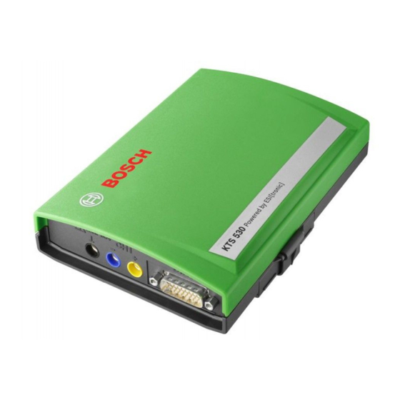
Bosch KTS 530 Operator Instructions Manual
Hide thumbs
Also See for KTS 530:
- Original instructions manual (170 pages) ,
- Original instructions manual (200 pages)
Table of Contents
en
14 | KTS 530 / KTS 540 / KTS 570 | Contents
Contents
1.
1.1
1.2
1.3
1.4
1.5
1.6
2.
2.1
2.2
2.3
2.4
2.5
2.5.2 T e r m in a l s tr ip
2.6
2.7
2.8
1 6 8 9 9 7 9 9 8 7
|
2 0 0 6 -0 9 -2 9
15
3.
15
3.1
15
3.2
15
3.3
15
3.4
15
15
4.
4.1
16
4.2
M a in te n a n c e
16
4.3
16
16
5.
16
5.1
16
5.2
17
5.3
17
5.4
17
17
( C H 1 a n d C H 2)
17
18
18
18
18
5.5
5.6
19
19
19
20
20
20
21
* )
Bosch Diagnostics
http://www.obd2be.com/
22
22
22
22
22
23
23
23
23
23
23
23
23
23
23
24
24
24
24
24
24
24
Table of Contents

Summary of Contents for Bosch KTS 530
-
Page 1: Table Of Contents
14 | KTS 530 / KTS 540 / KTS 570 | Contents Contents O p er a tor instr u c tions Initia l sta r t-u p Im p o r ta n t n o te s A s s e m b ly m o u n t... -
Page 2: O P Er A Tor Instr U C Tions
Operator instructions | KTS 530 / KTS 540 / KTS 570 | 15 O p er a tor instr u c tions Im portant info rm ation reg arding B luetooth Im portant notes Bluetooth is a wireless connection in the unlicensed Important notes on the agreement pertaining to copy- 2.4 Ghz-ISM-Band (ISM: Industrial, Scientific, Medical). -
Page 3: D Escription Of Unit
16 | KTS 530 / KTS 540 / KTS 570 | Description of unit D escription of unit R eq uirements A pplication 2.2.1 H ardw are KTS 530, KTS 540 and KTS 570 (hereinafter referred to as PC/Laptop with at least one free USBinterface. -
Page 4: D E Liv E R Y S P E C Ifi C A Tio N
Description of unit | KTS 530 / KTS 540 / KTS 570 | 17 Deliv ery specification System tester Description Order N umber 2.5.1 Diagnosis terminals/Measurement terminals System tester KTS 530 1 687 022 437 System tester KTS 540 1 687 022 436... -
Page 5: Functions Of L Eds A And B
18 | KTS 530 / KTS 540 / KTS 570 | Description of unit Bluetooth 2.5.3 Functions of L EDs A and B L ED A Function Measures 2.6.1 Bluetooth USB adapter Does not il- No data communica- Check connection... -
Page 6: Operation
Description of unit | KTS 530 / KTS 540 / KTS 570 | 19 Operation 2.7.2 Notes concerning controller diagnosis KTS 530 can only be connected with the PC/Laptop via KTS modules are either powered via the power the USB interface. KTS 540 and KTS 570 can be linked... -
Page 7: N O Te S C O N C E R N In G Th E M U Ltim E Te R
20 | KTS 530 / KTS 540 / KTS 570 | Description of unit Notes concerning faults 2.7.3 Notes concerning the multimeter and oscilloscope 2.8.1 Diagnosis hardware has not been found. Danger from high voltage! When the control unit diagnosis software was started... -
Page 8: Initializ Ing Bluetooth Drivers
Description of unit | KTS 530 / KTS 540 / KTS 570 | 21 2.8.3 Initializ ing Bluetooth drivers Select Express mode option. If the Bluetooth connection is faulty or absent or alter- Select < Next>. native remedial measures failed (see Chapter 2.8.1), Bluetooth devices will be searched and displayed. -
Page 9: I Nitial Start-Up
22 | KTS 530 / KTS 540 / KTS 570 | Initial start-up I nitial start-up If the ESI[tronic] has not been enabled yet, enable it now. Do not plug in the Bluetooth USB adapter until How to install and enable the ESI[tronic] is described req ues ted to do s o during ins tallation of the Blue- on the "ESI[tronic] DVD 1 Diagnosis and technology"... -
Page 10: Maintenance
± 0 .5 % of measurement range 1 0 0 V — 1 0 0 mV R esolution (depending on measuring range) Bosch Diagnostics 1 6 8 9 9 7 9 9 8 7 2 006 -09 -2 9 http://www.obd2be.com/... -
Page 11: A C And Effectiv E V Alue Measurement
24 | KTS 530 / KTS 540 / KTS 570 | Tech nical data Oscilloscope specifications 5.4.2 A C and effectiv e v alue measurement (CH1 and CH2) CH1 and CH2 are potential based (Measuring input CH1(–) or measuring input...


