
Related Manuals for LG BPM55


Summary of Contents for LG BPM55
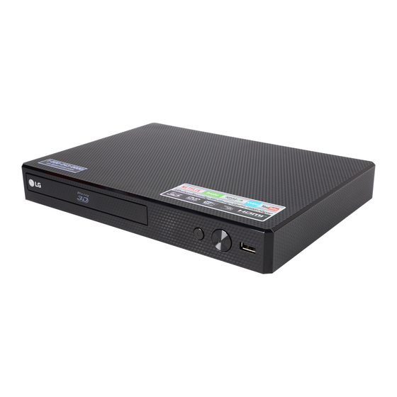
- Page 1 Internal Use Only Website http://biz.lgservice.com NETWORK 3D BLU-RAY DI S C / DVD PLAYER SERVICE MANUAL MODEL: BPM55 CAUTION BEFORE SERVICING THE UNIT, READ THE “SAFETY PRECAUTIONS” IN THIS MANUAL. P/NO : AFN76993005 DECEMBER, 2014...
- Page 2 CONTENTS SECTION 1 ..SUMMARY SECTION 2 ..CABINET & MAIN CHASSIS SECTION 3 ..ELECTRICAL SECTION 4 ..MT8563 F/E LOADER PART SECTION 5 ..REPLACEMENT PARTS LIST...
-
Page 3: Table Of Contents
SECTION 1 SUMMARY CONTENTS PRODUCT SAFETY SERVICING GUIDELINES FOR BLU-RAY DISC / DVD PLAYER PRODUCTS ..................1-3 SERVICING PRECAUTIONS .......................... 1-4 • GENERAL SERVICING PRECAUTIONS • INSULATION CHECKING PRODEDURE • ELECTROSTATICALLY SENSITIVE (ES) DEVICES FIRMWARE UPDATE GUIDE ......................... 1-5 SPECIFICATIONS ............................1-8... -
Page 4: Product Safety Servicing Guidelines For Blu-Ray Disc / Dvd Player Products
When servicing this product, under no circumstances should the original design be modified or altered without permission from LG Corporation. All components should be replaced only with types identical to those in the original circuit and their physical location, wiring and lead dress must conform to original layout upon completion of repairs. -
Page 5: Servicing Precautions
SERVICING PRECAUTIONS CAUTION: Before servicing the BLU-RAY DISC / DVD PLAYER cov- Electrostatically Sensitive (ES) Devices ered by this service data and its supplements and addends, Some semiconductor (solid state) devices can be damaged read and follow the SAFETY PRECAUTIONS. easily by static electricity. -
Page 6: Firmware Update Guide
FIRMWARE UPDATE GUIDE 1. COPY AN UPDATE FILE TO A MEDIA (USB OR CD-ROM) Update File Name: LG_BD_8100M60.ROM 1) An update fi le have to be copied onto the root of fi le system. 2) USB and CD-ROM are able to use fi rmware update. <... - Page 7 FIRMWARE UPDATE GUIDE 2. UPDATE FIRMWARE 1) Insert USB or CD-ROM which has an update fi le. 2) OSD responds to the insertion event. 3) OSD is shown as below. < Firmware Update OSD > OSD contents:...
- Page 8 FIRMWARE UPDATE GUIDE 3. DURING UPDATING 1) Progressive bar is shown on the update time repeatedly. 2) Tray is opened. 4. AFTER UPDATE COMPLETE 1) Power off / on automatically after update complete. 2) Tray will be closed.
-
Page 9: Specifications
SPECIFICATIONS • GENERAL AC adapter Model: WA-12M12FU Manufacturer: Asian Power Devices Inc. Input: 120 V~, 50-60 Hz 0.5 A Max. Output: 12 V Dimensions (W x H x D) Approx. 270 mm x 43 mm x 195 mm (10.62 x 1.69 x 7.68 Inches) Net Weight (Approx.) 0.87 kg (1.92 lbs) Operating temperature... - Page 10 SECTION 2 CABINET & MAIN CHASSIS CONTENTS EXPLODED VIEWS ............................2-2 1. CABINET AND MAIN FRAME SECTION ....................2-2 2. DECK MECHANISM SECTION (BM16EA5) .................... 2-3 3. PACKING ACCESSORY SECTION ......................2-4...
-
Page 11: Exploded Views
EXPLODED VIEWS 1. CABINET AND MAIN FRAME SECTION MAIN BOARD CABLE1 TIMER BOARD CABLE2 Wi-Fi MODULE... -
Page 12: Deck Mechanism Section (Bm16Ea5)
2. DECK MECHANISM SECTION (BM16EA5) 1439 1002 A001 1005 1001 1026 1003 1004 1030 1025 1437 1035 1437 1024 1025 1012 1049 1015 1024 1016 1013 1020 1011 A006 1019 1043 1018 1045 A005 1439... -
Page 13: Packing Accessory Section
3. PACKING ACCESSORY SECTION 801 Instruction Ass’y 808 Battery 900 Remote Control 833 AC Adapter 803 Packing 803 Packing 804 Bag 802 Box... - Page 14 SECTION 3 ELECTRICAL CONTENTS DIGITAL DISPLAY & MEDIA TRAINING MASTER ..................3-2 1. DISTORTED PICTURE ........................... 3-2 2. NO PICTURE ............................3-7 3. PICTURE COLOR ..........................3-12 4. NOISE/AUDIO PROBLEMS ........................3-14 5. MISCELLANEOUS ..........................3-17 6. BLU-RAY PLAYER ..........................3-26 ONE POINT REPAIR GUIDE ..........................
-
Page 15: Digital Display & Media Training Master
DIGITAL DISPLAY & MEDIA TRAINING MASTER Objective: To provide clear and concise guidelines for customer service agents to handle calls on box goods calls. 1. DISTORTED PICTURE 1-1. Lines on Picture Distorted picture refers to the customer getting video, but there is a problem with the video. Determine what cables the customer is using to connect What cables is the BD to the TV and if connected properly. - Page 16 DIGITAL DISPLAY & MEDIA TRAINING MASTER 1-2. Ghost Picture Distorted picture refers to the customer getting video, but there is a problem with the video. Determine what cables the customer is using to connect the BD to the TV and if connected properly. Refer to OM for connections. What cables is the customer Tighten any loose cables.
- Page 17 DIGITAL DISPLAY & MEDIA TRAINING MASTER 1-3. Rolling Picture Distorted picture refers to the customer getting video, but there is a problem with the video. Determine what cables the customer is using to connect the BD to the TV and if connected properly. Refer to OM for connections. What cables is the customer Tighten any loose cables.
- Page 18 DIGITAL DISPLAY & MEDIA TRAINING MASTER 1-4. Shaky Picture Distorted picture refers to the customer getting video, but there is a problem with the video. Determine what cables the customer is using to connect the BD to the TV and if connected properly. Refer to OM for connections. What cables is the customer Tighten any loose cables.
- Page 19 DIGITAL DISPLAY & MEDIA TRAINING MASTER 1-5. Blurry Picture Distorted picture refers to the customer getting video, but there is a problem with the video. Determine what cables the customer is using to connect the BD to the TV and if connected properly. Refer to OM for connections. What cables is the customer Tighten any loose cables.
-
Page 20: No Picture
DIGITAL DISPLAY & MEDIA TRAINING MASTER 2. NO PICTURE 2-1. Black Screen The entire screen is black. Determine what cables the customer is using to connect the BD to the TV and if connected properly. Refer to OM for connections. What cables is the customer Tighten any loose cables. - Page 21 DIGITAL DISPLAY & MEDIA TRAINING MASTER 2-2. Blue Screen The entire screen is a solid blue color. Determine what cables the customer is using to connect the BD to the TV and if connected properly. Refer to OM for connections. What cables is the customer Tighten any loose cables.
- Page 22 DIGITAL DISPLAY & MEDIA TRAINING MASTER 2-3. Snowy Screen A snowy picture is when black and white dots are all over the screen. Determine what cables the customer is using to connect the BD to the TV and if connected properly. Refer to OM for connections. What cables is the customer Tighten any loose cables.
- Page 23 DIGITAL DISPLAY & MEDIA TRAINING MASTER 2-4. No Signal A “no signal” message appears on the screen of the display. Determine what cables the customer is using to connect the BD to the TV and if connected properly. Refer to OM for connections. What cables is the customer Tighten any loose cables.
- Page 24 DIGITAL DISPLAY & MEDIA TRAINING MASTER 2-5. Invalid Format or Format Not Supported Make sure the display is HDCP compliant when using a DVI or Is the display HDMI connection. A lack of HDCP compliancy on the display may HDCP compliant? cause an invalid format or format not supported message to appear.
-
Page 25: Picture Color
DIGITAL DISPLAY & MEDIA TRAINING MASTER 3. PICTURE COLOR 3-1. No Color The video displays no color and only shows in black and white. Determine what cables the customer is using to connect the BD What cables is the customer to the TV and if connected properly. - Page 26 DIGITAL DISPLAY & MEDIA TRAINING MASTER 3-2. Poor Color The color is poor. Examples would be washed out colors, colors bleeding into one another, or a solid tint to a screen. Determine what cables the customer is using to connect the BD to What cables is the customer the TV and if connected properly.
-
Page 27: Noise/Audio Problems
DIGITAL DISPLAY & MEDIA TRAINING MASTER 4. NOISE/AUDIO PROBLEMS 4-1. No Audio The customer is not able to get audio. Determine what cables the customer is using to connect the BD to the TV and if connected properly. Refer to OM for connections. What cables is the customer Tighten any loose cables. - Page 28 DIGITAL DISPLAY & MEDIA TRAINING MASTER 4-2. Distorted Audio The audio sounds muffled, scratchy, or the audio skips. Determine what cables the customer is using to connect the BD to the TV and if connected properly. Refer to OM for connections. What cables is the customer Tighten any loose cables.
- Page 29 DIGITAL DISPLAY & MEDIA TRAINING MASTER 4-3. Humming/Clicking Noise The unit is making a humming noise or a clicking noise. BD’s make a slight hum when playing discs. Does the noise only A clicking noise or a noise interfering with audio may indicate a problem. happen when a disc Try multiple discs.
-
Page 30: Miscellaneous
DIGITAL DISPLAY & MEDIA TRAINING MASTER 5. MISCELLANEOUS 5-1. No Power The unit will not turn on. Is the unit plugged in? Is the unit plugged in? Does the unit turn on See if the unit will turn on when the power button the unit is pressed. when the power button If the unit turns on, then troubleshoot the remote control using is pressed on the unit? - Page 31 DIGITAL DISPLAY & MEDIA TRAINING MASTER 5-2. Disc Error The unit displays “disc error” when a disc is inserted into the BD player. Is the disc inserted into Make sure the disc has been inserted into the BD player properly. the BD player properly? The player can not read a disc inserted into the unit upside down.
- Page 32 DIGITAL DISPLAY & MEDIA TRAINING MASTER 5-3. Unit Locks Up Unit does not respond to any commands. If the unit will turn on or off with the button on the unit, Does the unit respond to troubleshoot the remote control. Please refer to the buttons on the unit? Remote Control Not Working call flow.
- Page 33 Please refer to the OM for instructions on how to program remote to TV. Customer wants to program a remote Does the customer want to other than Zenith or LG, the customer will need to contact program their remote? the manufacturer of the remote control. Codes do not work, remote is not compatible.
- Page 34 DIGITAL DISPLAY & MEDIA TRAINING MASTER 5-6. Will Not Play Disc The unit will not play a disc when a disc is inserted into the player. Is the disc inserted into Make sure the disc has been inserted into the BD player properly. the BD player properly? The player can not read a disc inserted into the unit upside down.
- Page 35 DIGITAL DISPLAY & MEDIA TRAINING MASTER 5-7. Disc Freezes or Skips The audio and video freeze and skip during play back of a BD or DVD disc. Is the disc inserted into Make sure the disc has been inserted into the BD player properly. the BD player properly? The player can not read a disc inserted into the unit upside down.
- Page 36 DIGITAL DISPLAY & MEDIA TRAINING MASTER 5-8. Can Access Menu, but Not Play a Movie The disc menu is displayed but the disc will not play. Go into the system information screen of the BD player. To access this menu, bring up the main menu. Go to TV aspect, Check the system information highlight 16:9, press 1397139 and hit enter.
- Page 37 DIGITAL DISPLAY & MEDIA TRAINING MASTER 5-10. Aspect Ratio The customer has bars on the top and bottom of the screen, the left and right of the screen, or both. A full screen movie played on a wide screen TV will have bars Is the movie on the left and right side of the TV.
- Page 38 DIGITAL DISPLAY & MEDIA TRAINING MASTER 5-11. My Unit Won’t be up-converted The customer has a problem with getting the unit to change resolutions to 480i/p, 720i/p, 1080i, or 1080p. Ask the customer to press stop to stop the disc from playing. Is the disc Ask the customer to press the resolution button to change the resolution.
-
Page 39: Blu-Ray Player
DIGITAL DISPLAY & MEDIA TRAINING MASTER 6. BLU-RAY PLAYER 6-1. Slow Loading Times for BD’s When a customer switches from one disc to another, Why does it take so long the lens have to be changed what causes the delay. to load my BD’s? BLU-RAY require different lasers to read the discs. -
Page 40: One Point Repair Guide
ONE POINT REPAIR GUIDE 1. NO POWER PROBLEM No power problem occurs when you power on the unit. 1-1. Adapter 1-1-1. Solution Replace the adapter. 1-1-2. How to troubleshoot (Countermeasure) 1) Check the 12 VA of JK806/ L150/ L155/ C151 on main board. 2) If it have 12 VA, refer to the next page for checking another reason. -
Page 41: Led Doesn't Light On
ONE POINT REPAIR GUIDE 2. LED DOESN’T LIGHT ON Timer board doesn’t work. 2-1. 5.1 VA abnormal 2-1-1. Solution Replace the IC150. 2-1-2. How to troubleshoot (Countermeasure) 1) Check the 5.1 VA of IC150 pin9 or pin10. 2) If 5.1 VA doesn’t come out, check the IC150 pin8 or pin13 (12 VA). If there is no 12 VA, check adapter (refer to 1-1-1 solution). - Page 42 ONE POINT REPAIR GUIDE 3. NO BOOTING WHEN YOU TURN THE UNIT ON When you turn on your set, it will blank/ no displaying Main Menu on Television/ Monitor, and it will not boot-up. 3-1. IC153 (No 3.3 VA) 3-1-1. Solution Replace IC153 on main board.
-
Page 43: No Booting When You Turn The Unit On
ONE POINT REPAIR GUIDE NO BOOTING WHEN YOU TURN THE UNIT ON When you turn on your set, it will blank/ no displaying Main Menu on Television/ Monitor, and it will not boot-up. 3-2. IC151 (No 3.3 V) 3-2-1. Solution Replace IC151 on main board. - Page 44 ONE POINT REPAIR GUIDE NO BOOTING WHEN YOU TURN THE UNIT ON When you turn on your set, it will blank/ no displaying Main Menu on Television/ Monitor, and it will not boot-up. 3-3. IC152 (No 1.5 V) 3-3-1. Solution Replace IC152 on main board.
- Page 45 ONE POINT REPAIR GUIDE NO BOOTING WHEN YOU TURN THE UNIT ON When you turn on your set, it will blank/ no displaying Main Menu on Television/ Monitor, and it will not boot-up. 3-4. IC150 (No 1.2 V) 3-4-1. Solution Replace IC150 on main board.
- Page 46 ONE POINT REPAIR GUIDE NO BOOTING WHEN YOU TURN THE UNIT ON When you turn on your set, it will blank/ no displaying Main Menu on Television/ Monitor, and it will not boot-up. 3-5. X501 3-5-1. Solution Replace X501 on main board. 3-5-2.
- Page 47 ONE POINT REPAIR GUIDE NO BOOTING WHEN YOU TURN THE UNIT ON When you turn on your set, it will blank/ no displaying Main Menu on Television/ Monitor, and it will not boot-up. 3-6. IC602 (NAND FLASH MEMORY) 3-6-1. Solution Replace IC602 on main board.
- Page 48 ONE POINT REPAIR GUIDE NO BOOTING WHEN YOU TURN THE UNIT ON When you turn on your set, it will blank/ no displaying Main Menu on Television/ Monitor, and it will not boot-up. 3-7. IC601 (DDR3 MEMORY) 3-7-1. Solution Replace IC601 on main board. 3-7-2.
- Page 49 ONE POINT REPAIR GUIDE NO BOOTING WHEN YOU TURN THE UNIT ON When you turn on your set, it will blank/ no displaying Main Menu on Television/ Monitor, and it will not boot-up. 3-8. IC501 (MPEG IC) 3-8-1. Solution Replace IC501 on main board. 3-8-2.
- Page 50 ONE POINT REPAIR GUIDE NO BOOTING WHEN YOU TURN THE UNIT ON When you turn on your set, it will blank/ no displaying Main Menu on Television/ Monitor, and it will not boot-up. 3-9. Main board 3-9-1. Solution Replace main board. 3-9-2.
-
Page 51: Bad Hdmi Video / Audio Output
ONE POINT REPAIR GUIDE 4. BAD HDMI VIDEO / AUDIO OUTPUT When unit is connected to HDMI TV using HDMI cable, picture shows bad color, no output or mixed color on the screen. But component output is OK. 4-1. JK802 (HDMI Jack) 4-1-1. -
Page 52: Wired Network Connection Error - (Option Part)
ONE POINT REPAIR GUIDE 5. WIRED NETWORK CONNECTION ERROR - (OPTION PART) When you connect online service (like Youtube or Netflix2.1) through the wired LAN, the “no connection” message appears. 5-1. JK803 (Ethernet Jack) 5-1-1. Solution Replace JK803 (Ethernet Jack) on main board. 5-1-2. -
Page 53: Wireless Network Connection Error - (Option Part)
ONE POINT REPAIR GUIDE 6. WIRELESS NETWORK CONNECTION ERROR - (OPTION PART) When you connect online service (like Youtube or Netflix2.1) through the Wi-Fi, the “no connection” message appears. 6-1. Wi-Fi Module 6-1-1. Solution Replace Wi-Fi module. 6-1-2. How to troubleshoot (Countermeasure) 1) Check you internet connection. -
Page 54: Electrical Troubleshooting Guide
ELECTRICAL TROUBLESHOOTING GUIDE 1. POWER SUPPLY ON MAIN BOARD No 3.3 V Is the Check 5.1 VA on IC150 pin10. Vcc supplied to D150 anode? Check C178 or replace D150. Is D150 output 5.1 VA? Is there Check voltage on IC501. signal at IC151 pin1? Check IC151 and replace. - Page 55 ELECTRICAL TROUBLESHOOTING GUIDE No 1.5 V Is the Check 3.3 V on IC151 pin3. 3.3 V supplied to IC152 pin3? Check IC150 and replace. No 1.2 V Is the Check 12 VA on JK806. Vcc 12 VA supplied to IC150 pin13? Is there Check PWR_CTL signal from IC501.
-
Page 56: System Part
ELECTRICAL TROUBLESHOOTING GUIDE 2. SYSTEM PART Power on IC501, LED is Check IC150, IC151, IC601, IC602 Vcc Turning On IC152, IC153 and adapter. 1.2V, 3.3VA, 3.3V, 1.5V X501 Replace X501. 27.000 MHz OK ? Replace Board Main IC501 MPEG IC. 5.1 VA Check IC150 pin9. - Page 57 ELECTRICAL TROUBLESHOOTING GUIDE IC501 Vcc “LG Logo” Check IC150, IC151, 1.2VA, 3.3VA, 3.3V,1.5V display on monitor IC152, IC153 and adapter. IC601 Check IC152 pin4. Vcc 1.5 V OK? X501 Replace X501. 27.000 MHz Signal Replace IC602 NF_ALE, NF_CLE (NAND flash).
-
Page 58: No Hdmi Output
ELECTRICAL TROUBLESHOOTING GUIDE 3. NO HDMI OUTPUT No HMDI audio / video output JK802 pin18 Check VCC 5 V from IC150. VCC 5 V OK? Check hot plug detect JK802 pin19 HPD signal from TV. about 3.3 V OK? Check IC501 MPEG IC Vcc Is there signal on or replace IC501 MPEG IC. -
Page 59: Waveforms Of Major Check Point
WAVEFORMS OF MAJOR CHECK POINT 1. SYSTEM PART - 1 IC501 X-TAL 27 MHz 3-46... -
Page 60: System Part - 2 (System Memory)
2. SYSTEM PART - 2 (SYSTEM MEMORY) IC601 BA0 IC601 WE# IC601 CAS# IC601 CK 3-47... -
Page 61: Hdmi Part
3. HDMI PART H_SDA H_SCL HDMI_CLK_N HDMI_0_N 3-48... -
Page 62: Wiring Diagrams
WIRING DIAGRAMS : FFC : Hardness HDMI JACK COAXIAL JACK 45 Pins 5 Pins 9 Pins 3-49... -
Page 63: Block Diagram
BLOCK DIAGRAM 3-50... -
Page 64: Circuit Diagrams
CIRCUIT DIAGRAMS 1. MAIN - DC-DC CIRCUIT DIAGRAM DC-DC EAX65983001_Rev1.4(6)_MAIN 2014.11.10 3-51 3-52... -
Page 65: Main - Mpeg Circuit Diagram
2. MAIN - MPEG CIRCUIT DIAGRAM MPEG : WAVEFORM NUMBER EAX65983001_Rev1.4(6)_MAIN 2014.11.10 3-53 3-54... -
Page 66: Main - Memory & Strap Circuit Diagram
3. MAIN - MEMORY & STRAP CIRCUIT DIAGRAM MEMORY & STRAP : WAVEFORM NUMBER EAX65983001_Rev1.4(6)_MAIN 2014.11.10 3-55 3-56... -
Page 67: Main - Front End Circuit Diagram
4. MAIN - FRONT END CIRCUIT DIAGRAM FRONT END EAX65983001_Rev1.4(6)_MAIN 2014.11.10 3-57 3-58... -
Page 68: Main - A/V Output Circuit Diagram
5. MAIN - A/V OUTPUT CIRCUIT DIAGRAM : WAVEFORM NUMBER A/V OUTPUT EAX65983001_Rev1.4(6)_MAIN 2014.11.10 3-59 3-60... -
Page 69: Timer Circuit Diagram
6. TIMER CIRCUIT DIAGRAM TIMER EAX66110701_Rev1.5(7)_TIMER 2014.11.10 3-61 3-62... -
Page 70: Circuit Voltage Chart
CIRCUIT VOLTAGE CHART Pin No. Desc. Standby Home Play IC150 TPS65252 Vin1 12.324 12.17 12.14 5.06 1.243 1.243 Vin2 12.324 12.17 12.14 USB Vin 5.06 USB Vout 5.06 5.06 IC151 LM37102D 4.81 4.24 4.24 Vout 3.354 3.352 IC152 AZ1117BH-ADJTRE1 3.29 Vout 1.51 1.51... -
Page 71: Printed Circuit Board Diagrams
PRINTED CIRCUIT BOARD DIAGRAMS 1. MAIN P.C. BOARD (TOP VIEW) (BOTTOM VIEW) 2. TIMER P.C. BOARD (TOP VIEW) (BOTTOM VIEW) 3-65 3-66... - Page 72 SECTION 4 MT8553/ MT8563 FRONT-END LOADER PART CONTENTS LD CHECK GUIDE ............................4-2 1. PURPOSE ..............................4-2 2. LD CHECK PROCEDURE ........................4-2 HOW TO USE THE SA RESET FUNCTION ..................4-3 1. PURPOSE ..............................4-3 2. REQUIRED SA RESET..........................4-3 3.
-
Page 73: Ld Check Guide
LD CHECK GUIDE 1. PURPOSE If LD (Laser Diode) have problem, disc reading problem can happen. So it is needed to check LD status. 2. LD CHECK PROCEDURE 1) Power on the set (then, mode is in home menu). 4 ) Check result is shown automatically. If you will see “PASS”, BD/DVD/CD LD status is OK. -
Page 74: How To Use The Sa Reset Function
HOW TO USE THE SA RESET FUNCTION 1. PURPOSE In order to insert the new SA adjustment values, it needs clearing SA initial values of the flash memory. 2. REQUIRED SA RESET - After changing traverse. - After changing main board assembly. - After changing main board flash IC. - Page 75 4) Insert BD-ROM SL disc. (Tray is opened automatically.) 5) If the disc is inserted, you will see “Wait...”. 6 ) If SA Adjustment is fi nished, you will see “PASS” and tray is opened automatically. 7) Press stop key twice to escape this special mode. Reference:...
-
Page 76: Major Ic Internal Block Diagram And Pin Description
MAJOR IC INTERNAL BLOCK DIAGRAM AND PIN DESCRIPTION 1. MT8553/ MT8563 PIN DESCRIPTION 1-1. Pin Function PIN NO. SYMBOL TYPE DESCRIPTION SERVO AUX1 Analog I/O Auxiliary Input. Alternateive Function : Signal Monitoring AVDD12 Analog Power(1.2V) Power Pin AVDD33_1 Analog Power(3.3V) Power Pin AVDD33_3 Analog Power(3.3V) - Page 77 PIN NO. SYMBOL TYPE DESCRIPTION PC RS232 serial receive data. The pin is spike-free at power-on stage. Alternate function : 3.3V LVTTL I/O, 1. High speed serial output port. (CLOCK) 5V-tolerance, 2. Internal monitored signal output FEGIO10 2, 4, 6, 8 mA PDR, 3.
- Page 78 PIN NO. SYMBOL TYPE DESCRIPTION Analog Input Input of Main Beam Signal (D) Analog Input Input of Sub-Beam Signal (E) Analog Input Input of Sub-Beam Signal (F) Analog Input Input of Sub-Beam Signal (G) Analog Input Input of Sub-Beam Signal (H) Multiplexer Output 1 for Signal Monitoring.
-
Page 79: Ic701 (Tpic2050): 9Ch Motor Drive With 3 Beam Laser Diode Driver
2. IC701 (TPIC2050) : 9ch motor drive with 3 beam laser diode driver 2-1. Block Diagram P12V P12V 0.1u 0.1u ICOM1 ICOM2 Charge XSLEEP pump SIOV 0.1 . Current limit ISENSE XSLEEP MCOM SPM Logic BEMF On chip SPM_ENA DAC PWM detector thermometer SIOV... - Page 80 2-2. Pin Function Name Description SLED1_P Sled1 positive output terminal SLED1_N Sled1 negative output terminal P12V_3 Power supply terminal for 12V drivers output SLED2_P Sled2 positive output terminal SLED2_N Sled2 negative output terminal PGND_2 GND terminal for 12V drivers C10V MISC The capacitance connection terminal for internal regulator MISC...
-
Page 81: Pick-Up Connector Terminal Pin Assignments
3. PICK-UP CONNECTOR TERMINAL PIN ASSIGNMENTS PIN NO. PIN NAME FUNCTION BLOCK Outer Focus (+) Outer Focus (-) Tracking (+) Actuator Inner Focus (+) Tracking (-) Inner Focus (-) MOTOR_A- Step Motor A- MOTOR_B- Step Motor B- CLD Motor MOTOR_A+ Step Motor A+ MOTOR_B+ Step Motor B+... -
Page 82: Block Diagram
BLOCK DIAGRAM NAND DDR3 1 GB 256/ 512 MB 5.1 CH Audio 2 CH MT8553 S/PDIF Motor MT8563 Driver HDMI HD+SD Decode Ethernet Monitor 800 MHz Cortex-A7 CVBS 400 MHz Audio DSP x 3 HDMI 1.4 Ethernet 4-11... - Page 83 4-12...