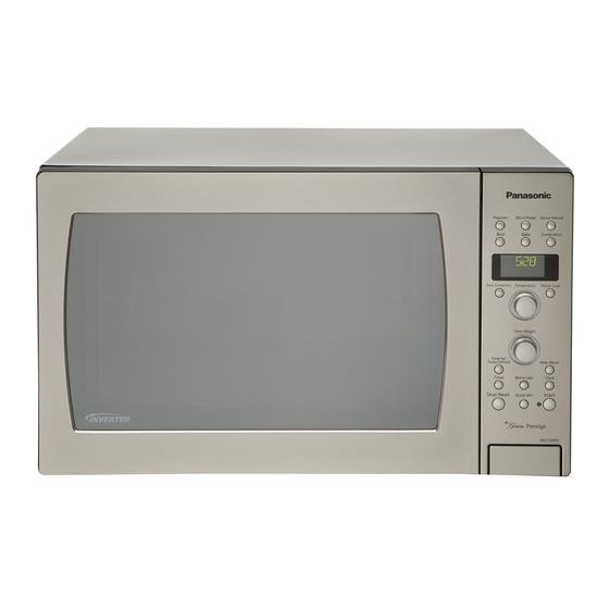
Panasonic NN-CD989S Service Manual
Hide thumbs
Also See for NN-CD989S:
- User manual ,
- Cookbook (49 pages) ,
- Operating instructions manual (36 pages)
Table of Contents
Please file and use this manual together with the service manual for Model No.NN-C980B(Order
No.MOD0003234C1).
TABLE OF CONTENTS
1 Safety Precautions----------------------------------------------- 2
2 Warning -------------------------------------------------------------- 3
3 Specifications ----------------------------------------------------- 4
4 Location of Controls and Components ------------------- 5
5 Test Mode ----------------------------------------------------------- 7
6 Service Mode ------------------------------------------------------ 8
7 Disassembly and Assembly Instructions ---------------10
Model No.
PAGE
8 Schematic Diagram -------------------------------------------- 12
9 Exploded View and Replacement Parts List ----------- 13
© Panasonic Corporation 2010 Unauthorized copy-
ing and distribution is a violation of law.
ORDER NO. MOD1002311AE
Microwave Oven
NN-CD989S
PAGE
Table of Contents

Summary of Contents for Panasonic NN-CD989S
-
Page 1: Table Of Contents
3 Specifications ----------------------------------------------------- 4 4 Location of Controls and Components ------------------- 5 5 Test Mode ----------------------------------------------------------- 7 6 Service Mode ------------------------------------------------------ 8 7 Disassembly and Assembly Instructions ---------------10 © Panasonic Corporation 2010 Unauthorized copy- ing and distribution is a violation of law. -
Page 2: Safety Precautions
5. Any serviceman who learns of any accident pertaining to microwave radiation leakage includng the oven operating with open door should immediately notify the appropriate address listed below and Center for Devices and Radiological Health,DHHS IN U.S.A. Panasonic Service and Technology Company (PSTC) 50 Meadowland Parkway, Secaucus, New Jersey 07094 Attention:Technical Service Division. -
Page 3: Warning
2 Warning... -
Page 4: Specifications
3 Specifications APH/RPH Power Source: 120V AC, 60Hz Power Requirement: Microwave 1,560 W Heater 1,500 W Output: Microwave 1,100 W : Full Power (IEC 705-88) Heater 1,400 W Microwave Frequency: 2,450 MHz Timer: Microwave 1 hour 30min. (30min. for High power) Heater 9 hours Outside Dimensions:... -
Page 5: Location Of Controls And Components
4 Location of Controls and Components 4.1. CONTROL PANEL... -
Page 6: Operation Guide
4.2. OPERATION GUIDE The display defaults to English,LB-F,and Operation Guide On. If you desire another option,see below for instructions. A change in language or measurement must be chosen directly after plugging in the oven. • LANGUAGE CHOICE Press More/Less Button Choice ENGLISH -... -
Page 7: Test Mode
5 Test Mode 5.1. COMPONENT TEST PROCEDURE 5.1.1. Humidity Sensor and Digital Programmer Circuit In order to determine if the humidity sensor fanction of the digital programmer circuit is in working order or not, do the following test 1. Place a water load in the oven. 2. -
Page 8: Service Mode
6 Service Mode 6.1. OPERATION AND DIGITAL PROGRAMMER CIRCUIT TEST PROCEDURE... - Page 9 6.2. SENSOR COOKING...
-
Page 10: Disassembly And Assembly Instructions
7 Disassembly and Assembly Instructions 7.1. CAUTION WHEN REPLACING INVERTER PCB 1. Remove 2 high voltage lead wires from magnetron. 2. Remove 2 lead wires from inverter PCB. 3. Remove 1 screw holding air guide. 4. Remove 2 screws holding noise filter from bottom. 5. -
Page 11: Disassembly And Parts Replacement Procedure
7.2. DISASSEMBLY AND PARTS REPLACEMENT PROCEDURE 7.2.1. PC board Au and PC board Du. NOTE:Be sure to ground any static electric charge buit up on your body, before handling the PC boards. 1. Disconnect all connectors from PC board Du. 6. -
Page 12: Schematic Diagram
8 Schematic Diagram... -
Page 13: Exploded View And Replacement Parts List
9 Exploded View and Replacement Parts List 9.1. EXPLODED VIEW AND PARTS LIST... -
Page 16: Door Assembly
9.3. DOOR ASSEMBLY Safety Ref. Part No. Part Name & Description Pcs/Set Remarks ANE0245X00AP DHHS LABEL XTBANE4+12FK SCREW 4X12 (FOR D8) A300B5450AP UPPER HINGE A302A7V2APS DOOR A (U) NOTE 1 A302K6660QP DOOR E (U) A30186660QP DOOR KEY A A30214000AP DOOR KEY SPRING A30856660QP DOOR C A33816E00AP... -
Page 17: Escutcheon Base Assembly
9.4. ESCUTCHEON BASE ASSEMBLY Safety Ref. Part No. Part Name & Description Pcs/Set Remarks A01576E00AP NAME LABEL A01577V20RP NAME LABEL A603Y7V20AP PC BOARD W/COMPONENT D.P.CIRCUIT A603L7V20AP PC BOARD W/COMPONENT APH D.P.CIRCUIT A603L7V20RP PC BOARD W/COMPONENT RPH D.P.CIRCUIT A66167F40QP FLAT CABLE A80096E00AP INDICATOR A A80097V20CP... -
Page 18: Packing And Accessories
9.5. PACKING AND ACCESSORIES Safety Ref. Part No. Part Name & Description Pcs/Set Remarks A000B7V20AP COOK BOOK A00037V20AP INSTRUCTION BOOK A00037V20RP INSTRUCTION BOOK A01027V20AP PACKING CASE PAPER A01046670AP UPPER FILLER A01056670AP LOWER FILLER A01065130AP VINYL COVER ANE0107580AP DOOR SHEET A01086660QP TRAY PACKING A0113660QP TRAY STYROL... -
Page 19: Wiring Material
9.6. WIRING MATERIAL Safety Ref. Part No. Part Name & Description Pcs/Set Remarks A030A7V20AP LEAD WIRE HARNESS A030E4X00AP LEAD WIRE A03536660QP LEAD WIRE A03536670AP LEAD WIRE...


