Emerson UNIDRIVE M600 Getting Started Manual
Hide thumbs
Also See for UNIDRIVE M600:
- Installation manual (46 pages) ,
- User manual (198 pages) ,
- Installation manual (102 pages)

Related Manuals for Emerson UNIDRIVE M600


Summary of Contents for Emerson UNIDRIVE M600
- Page 1 Getting Started Guide Unidrive M600 Part Number: 0478-0045-02 Issue: 2 www.controltechniques.com...
- Page 2 Original Instructions For the purposes of compliance with the EU Machinery Directive 2006/42/EC. General Information This guide covers the basic information that is required to set-up and run the drive, in applications where a drive malfunction does not result in a mechanical hazard. When the drive is used in a safety related application, i.e.
-
Page 3: Table Of Contents
Quick start connections ..................54 Quick Start / start-up ..................... 59 NV Media Card Operation .................66 Introduction ......................66 NV Media Card support ..................67 Transferring data ....................68 Further information ...................69 Diagnostics ......................69 Unidrive M600 Getting Started Guide Issue Number: 2... -
Page 4: Safety Information
Environmental limits Instructions in this guide regarding transport, storage, installation and use of the drive must be complied with, including the specified environmental limits. Drives must not be subjected to excessive physical force. Unidrive M600 Getting Started Guide Issue Number: 2... - Page 5 Some parameters have a profound effect on the operation of the drive. They must not be altered without careful consideration of the impact on the controlled system. Measures must be taken to prevent unwanted changes due to error or tampering. Unidrive M600 Getting Started Guide Issue Number: 2...
-
Page 6: Electrical Installation
The drive contains capacitors that remain charged to a potentially lethal voltage after the AC supply has been disconnected. If the drive has been energized, the AC supply must be isolated at least ten minutes before work may continue. Unidrive M600 Getting Started Guide Issue Number: 2... -
Page 7: Product Information
Product information This guide covers the Unidrive M600 product. Table 2-1 Supported operating modes Supported operating modes Product Open- RFC-A RFC-S RFC-A RFC-S Regen Loop Sensorless Sensorless Unidrive M600 * Possible via an option module. Model number The way in which the model numbers for the Unidrive M product range is formed is illustrated below:... -
Page 8: Nameplate Description
Serial number Output voltage Approvals * This label is only applicable to size 7 and above. Refer to Figure 2-1 Model number on page 7 for further information relating to the labels. Unidrive M600 Getting Started Guide Issue Number: 2... -
Page 9: Ratings
(B2) 2 x 95 2 x 120 09202190 2 x 4/0 (B1) (B2) 2 x 120 10202830 2 x 250 (B1) 2 x 120 (B2) 2 x 150 10203000 2 x 250 Unidrive M600 Getting Started Guide Issue Number: 2... - Page 10 2 x 1 (B2) 2 x 50 09501310 2 x 1 (B2) 2 x 70 10501520 (B2) 2 x 70 2 x 2/0 2 x 2/0 (B2) 2 x 95 10501900 (B2) Unidrive M600 Getting Started Guide Issue Number: 2...
- Page 11 The time allowed in the overload region is proportionally reduced at very low output frequency on some drive ratings. The maximum overload level which can be attained is independent of the speed. NOTE Unidrive M600 Getting Started Guide Issue Number: 2...
- Page 12 10501520, 10501900, 10601500, 10601780 INL 602 4401-0184 * This may represent a more economical solution where operating temperature and cooling requirements are observed. Refer to the Drive User Guide for further information. Unidrive M600 Getting Started Guide Issue Number: 2...
-
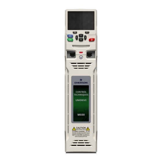
Page 13: Drive Features
8. Relay connections 13. Internal EMC filter 18. Ground connections 4. Status LED 9. Control connections 14. DC bus + 5. Option module slot 1 10. Communications port 15. DC bus - Unidrive M600 Getting Started Guide Issue Number: 2... -
Page 14: Options / Accessories
Figure 2-4 Drive features and options 1. Keypad 4. Option module slot 3 7. NV media card 2. Option module slot 1 5. CT Comms cable 3. Option module slot 2 6. Internal braking resistor Unidrive M600 Getting Started Guide Issue Number: 2... - Page 15 DC terminal cover grommets, terminal nuts, supply and motor connector and finger guard grommets are provided with the drive. For more information refer to the label on the accessory kit box supplied with the drive. Unidrive M600 Getting Started Guide Issue Number: 2...
-
Page 16: Mechanical Installation
If the drive has been used at high load levels for a period of time, the heatsink can reach temperatures in excess of 70 °C (158 °F). Human contact with the heatsink should be prevented. WARNING Unidrive M600 Getting Started Guide Issue Number: 2... -
Page 17: Drive Dimensions
Drive dimensions Figure 3-1 Drive dimensions Size 3.27 7.87 4.88 14.37 5.63 7.95 8.27 8.94 10.63 29.65 12.21 11.42 9E and 10 1069 42.09 12.21 11.38 Unidrive M600 Getting Started Guide Issue Number: 2... -
Page 18: Surface Mounting
220 mm (8.66 in) 7.0 mm 196 mm 10 mm (0.28 in) (7.72 in) (0.39 in) 6.0 mm (0.24 in) 378 mm (14.88 in) ∅ 7.0 mm (0.27 in) ∅9mm (0.35 in) Unidrive M600 Getting Started Guide Issue Number: 2... - Page 19 (1.02 in) 9 mm (0.35 in) Æ 9 mm (0.35 in) x 4 holes 26 mm (1.02 in) 257 mm (10.12 in) 10 mm (0.39 in) Æ 9 mm (0.35 in) (4 holes) Unidrive M600 Getting Started Guide Issue Number: 2...
-
Page 20: Terminal Size And Torque Settings
M6 Nut (10 mm AF) 6.0 N m (4.42 Ib ft) M8 Nut (13 mm AF) 12.0 N m (8.85 Ib ft) M10 Nut (17 mm AF) 8 to 10 15.0 N m (11.1 Ib ft) Unidrive M600 Getting Started Guide Issue Number: 2... -
Page 21: Enclosure
³100 mm drive in all directions (4 in) External controller Signal cables Plan for all signal cables to be routed at least 300 mm (12 in) from the drive and any power cable Unidrive M600 Getting Started Guide Issue Number: 2... -
Page 22: Emc Filters
2 N m (1.47 lb ft). Figure 3-6 Removal of the size 4 internal EMC filter To electrically disconnect the Internal EMC filter, remove the screw (1) as highlighted above. Unidrive M600 Getting Started Guide Issue Number: 2... - Page 23 Finally remove the M4 Torx internal EMC filter removal screw (3) to electrically disconnect the internal EMC filter. Figure 3-8 Removal of the size 6 internal EMC filter To electrically disconnect the Internal EMC filter, remove the screw (1) as highlighted above. Unidrive M600 Getting Started Guide Issue Number: 2...
- Page 24 The line to ground varistors should only be removed in special circumstances such as ungrounded supplies with more than one source, for example on ships. Contact the supplier of the drive for more information. Unidrive M600 Getting Started Guide Issue Number: 2...
- Page 25 To avoid a fire hazard and maintain validity of the UL listing, adhere to the specified tightening torques for the power and ground terminals. WARNING For further information refer to the Drive User Guide. Unidrive M600 Getting Started Guide Issue Number: 2...
-
Page 26: Electrical Installation
If the motor load is capable of rotating the motor when the supply is disconnected, then the motor must be isolated from the drive before gaining access to any live parts. Unidrive M600 Getting Started Guide Issue Number: 2... -
Page 27: Supply Types
3 under the following conditions: • The fault-clearing capacity must be sufficient for the installation Fuse types The fuse voltage rating must be suitable for the drive supply voltage. Unidrive M600 Getting Started Guide Issue Number: 2... -
Page 28: Power Connections
Thermal braking overload resistor protection device Internal EMC filter Ground connection studs Additional ground connection AC Connections Optional EMC filter Optional line reactor Fuses Motor Optional ground Mains connection Supply Supply Ground Unidrive M600 Getting Started Guide Issue Number: 2... - Page 29 DC / Brake connections Thermal overload protection Optional device braking resistor Additional ground connection Ground connection studs AC Connections Optional EMC filter Optional line reactor Fuses Motor Optional ground Mains connection Supply Supply Ground Unidrive M600 Getting Started Guide Issue Number: 2...
- Page 30 Fuses Motor Optional ground Mains connection Supply Supply Ground The upper terminal block (1) is used for AC supply connection. The lower terminal block (2) is used for Motor connection. Unidrive M600 Getting Started Guide Issue Number: 2...
- Page 31 Optional device braking resistor DC - DC + AC Connections Motor Connections Ground connection studs Optional EMC filter Optional line reactor Fuses Motor Optional ground Mains connection Supply Supply Ground Unidrive M600 Getting Started Guide Issue Number: 2...
- Page 32 Figure 4-5 Size 7 and 8 power and ground connections (size 7 shown) Input connections Mains Supply Supply ground Fuses Optional line reactor Optional EMC filter +DC -DC Output connections Thermal Optional overload braking protection resistor device Motor Optional ground connection Unidrive M600 Getting Started Guide Issue Number: 2...
- Page 33 A separate line reactor (INLXXX) must be used for size 9E and 10. Failure to provide sufficient reactance could damage or reduce the service life of the drive. Refer to Table 2-8 Size 9E and 10 model and line reactor part numbers on page 12. CAUTION Unidrive M600 Getting Started Guide Issue Number: 2...
-
Page 34: Ground Connections
The drive must be grounded by a connection capable of carrying the prospective fault current until the protective device (fuse, etc.) disconnects the AC supply. WARNING The ground connections must be inspected and tested at appropriate intervals. Unidrive M600 Getting Started Guide Issue Number: 2... -
Page 35: Braking Resistor Values
10601780 422.4 06400420 39.8 * Resistor tolerance: ±10 %. 06400470 32.7 07400660 41.6 75.2 07400770 50.6 07401000 96.6 60.1 08401340 140.9 08401570 98.6 09402000 118.6 282.9 09402240 156.9 10402700 198.2 10403200 237.6 Unidrive M600 Getting Started Guide Issue Number: 2... -
Page 36: Communications Connections
50 mm (2 in) long. A full 360 ° termination of the shield to the terminal housing of the motor is beneficial. Unidrive M600 Getting Started Guide Issue Number: 2... -
Page 37: Control Connections
0V to 0V Connection Connection at motor at drive Cable Cable Ground clamp shield shield on shield Control connections For information on control connections, refer to the back cover of this guide. Unidrive M600 Getting Started Guide Issue Number: 2... -
Page 38: Getting Started
2. Start reverse (Auxiliary button) 3. Start forward 4. Navigation keys (x4) 5. Stop / Reset (red) button 6. Enter button The red stop button is also used to reset the drive. NOTE Unidrive M600 Getting Started Guide Issue Number: 2... -
Page 39: Keypad Operation
Start reverse button - Used to control the drive if keypad mode is selected and the reverse button is activated. • Stop / Reset button - Used to reset the drive. In keypad mode can be used for 'Stop'. Unidrive M600 Getting Started Guide Issue Number: 2... - Page 40 Do not change parameter values without careful consideration; incorrect values may cause damage or a safety hazard. WARNING When changing the values of parameters, make a note of the new values in case they NOTE need to be entered again. Unidrive M600 Getting Started Guide Issue Number: 2...
-
Page 41: Menu 0
Where S signifies the option module slot number and the mm.ppp 00.005 signifies the menu and the parameter 00.004 00.003 number of the option module's internal 00.002 00.001 menus and parameter. Moves between Menus Unidrive M600 Getting Started Guide Issue Number: 2... -
Page 42: Advanced Menus
Onboard user programming application menu Slot 1 Slot 1 option menus* Slot 2 Slot 2 option menus* Slot 3 Slot 3 option menus* * Only displayed when the option modules are installed. Unidrive M600 Getting Started Guide Issue Number: 2... -
Page 43: Changing The Operating Mode
* If the drive is in the under voltage state (i.e. when the control terminal 1 & 2 are being supplied from a low voltage DC supply) a value of 1001 must be entered into Pr mm.000 to perform a save function. Unidrive M600 Getting Started Guide Issue Number: 2... -
Page 44: Restoring Parameter Defaults
Not visible The default settings of the drive are Parameter Access Level Menu 0 and User Security Open i.e. read / write access to Menu 0 with the advanced menus not visible. Unidrive M600 Getting Started Guide Issue Number: 2... -
Page 45: Basic Parameters (Menu 0)
Current Torque Mode 00.014 {04.011} 0 or 1 0 to 5 RW Num Selector Fast (0), Ramp Mode Fast (0), 00.015 {02.004} Standard (1), Standard (1) Select Standard (1) Std boost (2) Unidrive M600 Getting Started Guide Issue Number: 2... - Page 46 7 1 EP M (14), 7 1 OP M (15) 300 (0), 600 (1), 1200 (2), 2400 (3), 00.036 Serial Baud Rate {11.025} 4800 (4), 9600 (5), 19200 (6), 38400 19200 (6) (7), 57600 (8), 76800 (9), 15200 (10) Unidrive M600 Getting Started Guide Issue Number: 6...
- Page 47 RFC Low 00.054 {05.064} Non- salient Speed Mode salient Low Speed 0.0 to 20.0 00.055 Sensorless {05.071} 1000.0 RW Num Mode Current 0.000 to 0.000 00.056 No-load Lq {05.072} 500.000 RW Num Unidrive M600 Getting Started Guide Issue Number: 2...
- Page 48 -100 to 00.060 {05.082} -50 % RW Num Inductance Measurement Lq At The 0.000 to 0.000 00.061 Defined Id Test {05.084} 500.000 RW Num Current RW = Read Write, RO = Read Only. Unidrive M600 Getting Started Guide Issue Number: 6...
-
Page 49: Parameter Descriptions
Load parameters with standard (50 Hz) defaults Reset 60Hz Defs Load parameters with US (60 Hz) defaults Reset modules Reset all option modules Read Enc.NP P1 No function Read Enc.NP P2 No function Unidrive M600 Getting Started Guide Issue Number: 2... - Page 50 * See section 8 NV Media Card Operation on page 66 for more information on these functions. ** These functions do not require a drive reset to become active. All other functions require a drive reset to initiate the function. Unidrive M600 Getting Started Guide Issue Number: 6...
- Page 51 Unidrive M600 Getting Started Guide Issue Number: 2...
- Page 52 Read-only (RO) Read-only (RO) Output Output 00.XXX 00.XXX parameter parameter terminals terminals The parameters are all shown in their default settings The parameters are all shown in their default settings Unidrive M600 Getting Started Guide Issue Number: 6...
- Page 53 Dynamic V to F Feedback Select 00.010 Power stage Maximum Switching 00.041 Sensorless Frequency position 00.011 Output Frequency estimator RFC-A Current RFC-S Magnitude 00.013 00.012 Torque Producing Current Magnetising Current Resistor optional Unidrive M600 Getting Started Guide Issue Number: 2...
-
Page 54: Running The Motor
Open loop mode Induction motor RFC - A sensorless (without feedback position) Induction motor with speed feedback Permanent magnet motor with speed and RFC - S sensorless (without position feedback) position feedback Unidrive M600 Getting Started Guide Issue Number: 2... - Page 55 This must be wired to interrupt the AC supply in the event of a fault. This is not required if the optional internal braking resistor is used L1 L2 RFC-A RFC-S Sensorless Sensorless Unidrive M600 Getting Started Guide Issue Number: 2...
- Page 56 This must be wired to interrupt the AC supply in the L1 L2 event of a fault. This is not required if the optional internal braking resistor is used RFC-S RFC-A Sensorless Sensorless Unidrive M600 Getting Started Guide Issue Number: 2...
- Page 57 This must be wired to interrupt the AC supply in the L1 L2 event of a fault. This is not required if the optional internal braking resistor is used RFC-A RFC-S Sensorless Sensorless Unidrive M600 Getting Started Guide Issue Number: 2...
- Page 58 AC supply in the event of a fault. This is not required if the optional internal braking resistor is used RFC-S RFC-A Sensorless Sensorless *Required for size 9E and 10. Unidrive M600 Getting Started Guide Issue Number: 2...
-
Page 59: Quick Start / Start-Up
Pr 10.031 and Pr 10.061 are set correctly, otherwise 0.03 0.04 premature ‘Brake R Too Hot’ trips may be seen). Motor The motor thermistor can be selected in Pr 07.015. Refer to thermistor Pr 07.015 for further information. set-up Unidrive M600 Getting Started Guide Issue Number: 2... - Page 60 Select 'Save Parameters' in Pr mm.000 (alternatively enter a Save value of 1000 in Pr mm.000) and press the red reset parameters button or toggle the reset digital input. Drive is now ready to run Unidrive M600 Getting Started Guide Issue Number: 2...
- Page 61 Pr 10.061 are set correctly, otherwise premature ‘Brake R Too Hot’ rates 0.03 0.04 trips may be seen). Motor The motor thermistor can be selected in Pr 07.015. Refer to thermistor Pr 07.015 for further information. set-up Unidrive M600 Getting Started Guide Issue Number: 2...
- Page 62 Select 'Save Parameters' in Pr mm.000 (alternatively enter a value of Save 1000 in Pr mm.000) and press red reset button or toggle the parameters reset digital input. Drive is now ready to run Unidrive M600 Getting Started Guide Issue Number: 2...
- Page 63 Pr 00.015 = FAST. Also ensure rates Pr 10.030, Pr 10.031 and Pr 10.061 are set correctly, 0.03 0.04 otherwise premature ‘Brake R Too Hot’ trips may be seen). Unidrive M600 Getting Started Guide Issue Number: 2...
- Page 64 Select 'Save Parameters' in Pr mm.000 (alternatively enter a Save parameters value of 1000 in Pr mm.000) and press red reset button or toggle the reset digital input. Drive is now ready to run Unidrive M600 Getting Started Guide Issue Number: 2...
- Page 65 Select 'Save Parameters' in Pr mm.000 (alternatively enter a value of 1000 Save in Pr mm.000) and press red reset button or toggle the reset parameters digital input. Drive is now ready to run Unidrive M600 Getting Started Guide Issue Number: 2...
-
Page 66: Nv Media Card Operation
1. Installing the NV Media Card 2. NV Media Card installed NV Media Card Part number SD Card Adaptor (memory card not included) 3130-1212-03 8 kB SMARTCARD 2214-4246-03 64 kB SMARTCARD 2214-1006-03 Unidrive M600 Getting Started Guide Issue Number: 2... -
Page 67: Nv Media Card Support
The card should not be removed during data transfer, as the drive will produce a trip. If this occurs then either the transfer should be reattempted or in the case of a card to drive transfer, default parameters should be loaded. Unidrive M600 Getting Started Guide Issue Number: 2... -
Page 68: Transferring Data
60yyy folder. The command code will not be cleared until the drive and all option data have been loaded. Unidrive M600 Getting Started Guide Issue Number: 2... -
Page 69: Further Information
Further information Diagnostics For further information on diagnostics including trips and alarms, refer to the Drive User Guide. Unidrive M600 Getting Started Guide Issue Number: 2... - Page 70 Polarised signal 41 42 connectors +24V input Analog frequency/speed reference 1 Single-ended Non-inverting input signal Inverting input Non-inverting input Differential signal Inverting input +10V output Analog frequency/speed Analog input 2 reference 2 Analog input 3 Analog input 3 Analog output 1 Speed / frequency Analog output 2 Torque (active...