Table of Contents
Quick Links
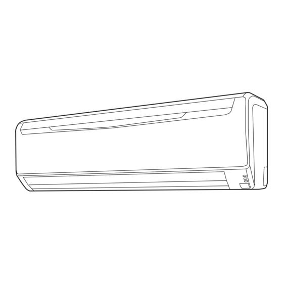
AIR CONDITIONER
INDOOR UNIT (Wall Mounted Type)
For authorized service personnel only.
• Installation must be performed in accordance with the requirement of NEC and CEC
by authorized personnel only.
1. SAFETY PRECAUTIONS
1.1. IMPORTANT! Please read before starting
This air conditioning system meets strict safety and operating standards.
As the installer or service person, it is an important part of your job to install or service the
system so it operates safely and effi ciently.
For safe installation and trouble-free operation, you must:
• Carefully read this instruction booklet before beginning.
• Follow each installation or repair step exactly as shown.
• Observe all local, state, and national electrical codes.
• Pay close attention to all warning and caution notices given in this manual.
This symbol refers to a hazard or unsafe practice which can
WARNING
result in severe personal injury or death.
This symbol refers to a hazard or unsafe practice which can
result in personal injury and the potential for product or prop-
CAUTION
erty damage.
• Hazard alerting symbols
Electrical
Safety/alert
If Necessary, Get Help
These instructions are all you need for most installation sites and maintenance conditions.
If you require help for a special problem, contact our sales/service outlet or your certifi ed
dealer for additional instructions.
In Case of Improper Installation
The manufacturer shall in no way be responsible for improper installation or maintenance
service, including failure to follow the instructions in this document.
1.2. Special precautions
When Wiring
ELECTRICAL SHOCK CAN CAUSE SEVERE PERSONAL INJURY OR DEATH. ONLY A
QUALIFIED, EXPERIENCED ELECTRICIAN SHOULD ATTEMPT TO WIRE THIS SYS-
TEM.
• Do not supply power to the unit until all wiring and tubing are completed or reconnected
and checked.
• Highly dangerous electrical voltages are used in this system. Carefully refer to the wir-
ing diagram and these instructions when wiring. Improper connections and inadequate
earthing (grounding) can cause accidental injury or death.
• Earth (Ground) the unit following local electrical codes.
• Connect all wiring tightly. Loose wiring may cause overheating at connection points and
a possible fi re hazard.
When Transporting
Be careful when picking up and moving the indoor and outdoor units. Get a partner to
help, and bend your knees when lifting to reduce strain on your back. Sharp edges or thin
aluminum fi ns on the air conditioner can cut your fi ngers.
When Installing...
...In a Ceiling or Wall
Make sure the ceiling/wall is strong enough to hold the unit's weight. It may be necessary
to construct a strong wood or metal frame to provide added support.
INSTALLATION MANUAL
PART No. 9318739183
Contents
1.
SAFETY PRECAUTIONS .................................................................. 1
2.
ABOUT THIS PRODUCT................................................................... 2
3.
GENERAL SPECIFICATIONS ........................................................... 2
4.
SELECTING THE INSTALLATION LOCATION ................................. 3
5.
INSTALLATION WORK ..................................................................... 3
6.
ELECTRICAL WIRING ..........................................................................5
7.
FINISHING ........................................................................................ 6
8.
FRONT PANEL REMOVAL AND INSTALLATION ............................. 7
9.
REMOTE CONTROLLER INSTALLATION ........................................ 7
10. OPTIONAL KIT INSTALLATION ........................................................ 7
11. FUNCTION SETTING........................................................................ 9
12. TEST RUN ........................................................................................11
13. CUSTOMER GUIDANCE .................................................................11
14. ERROR CODES ...............................................................................11
...In a Room
Properly insulate any tubing run inside a room to prevent "sweating" that can cause drip-
ping and water damage to walls and fl oors.
...In an Area with High Winds
Securely anchor the outdoor unit down with bolts and a metal frame.
Provide a suitable air baffl e.
...In a Snowy Area (for Heat Pump-type Systems)
Install the outdoor unit on a raised platform that is higher than drifting snow.
When Connecting Refrigerant Tubing
• Keep all tubing runs as short as possible.
• Use the fl are method for connecting tubing.
• Apply refrigerant lubricant to the matching surfaces of the fl are and union tubes before
connecting them, then tighten the nut with a torque wrench for a leak-free connection.
• Check carefully for leaks before opening the refrigerant valves.
When Servicing
• Turn the power OFF at the main circuit breaker panel before opening the unit to check or
repair electrical parts and wiring.
• Keep your fi ngers and clothing away from any moving parts.
• Clean up the site after you fi nish, remembering to check that no metal scraps or bits of
wiring have been left inside the unit being serviced.
• After installation, explain correct operation to the customer, using the operating manual.
WARNING
Never touch electrical components immediately after the power supply has been turned
off. Electric shock may occur. After turning off the power, always wait 5 minutes before
touching electrical components.
If refrigerant leaks while work is being carried out, ventilate the area. If the refrigerant
comes in contact with a fl ame, it produces a toxic gas.
CAUTION
Do not attempt to install the air conditioner or a part of the air conditioner by yourself.
This unit must be installed by qualifi ed personnel with a capacity certifi cate for handling
refrigerant fl uids. Refer to regulation and laws in use on installation place.
This unit is part of a set constituting an air conditioner. It must not be installed alone or
with non-authorized by the manufacturer.
Always use a separate power supply line protected by a circuit breaker operating on all
wires with a distance between contact of 1/8 in. (3 mm) for this unit.
The unit must be correctly earthed (grounded) and the supply line must be equipped
with a differential breaker in order to protect the persons.
The units are not explosion proof and therefore should not be installed in explosive
atmosphere.
When moving, consult authorized service personnel for disconnection and installation
of the unit.
Do not place any other electrical products or household belongings under indoor unit or
outdoor unit.
Dripping condensation from the unit might get them wet, and may cause damage or
malfunction of your property.
All Fujitsu General products are manufactured to metric units and tolerances. United
States customary units are provided for reference only. In cases where exact dimen-
sions and tolerances are required, always refer to metric units.
En-1
Table of Contents

Related Manuals for Fujitsu 9318739183


Summary of Contents for Fujitsu 9318739183
-
Page 1: Table Of Contents
fi ns on the air conditioner can cut your fi ngers. malfunction of your property. When Installing... All Fujitsu General products are manufactured to metric units and tolerances. United ...In a Ceiling or Wall States customary units are provided for reference only. In cases where exact dimen- Make sure the ceiling/wall is strong enough to hold the unit’s weight. -
Page 2: About This Product
2. ABOUT THIS PRODUCT 2.4. Accessories The following installation accessories are supplied. Use them as required. 2.1. Precautions for using R410A refrigerant Name and Shape Q’ty Name and Shape Q’ty Operating Manual Drain hose insulation The basic installation work procedures are the same as conventional refrigerant (R22) models. -
Page 3: Selecting The Installation Location
5. INSTALLATION WORK CAUTION Install heat insulation around both the gas and liquid pipes. Failure to do so may cause water leaks. 5.1. Installation dimensions Use heat insulation with heat resistance above 248 °F (120 °C). Reverse cycle model only. 3-1/8 in. - Page 4 • For left piping and left rear piping, align the marks on the wall hook bracket and shape the 5.4. Installing the wall hook bracket connection pipe. • Bend the connection piping at a bend radius of 3-15/16 in. (100 mm) or more and install (1) Install the wall hook bracket so that it is correctly positioned horizontally and vertically.
-
Page 5: Electrical Wiring
Dimension A [in. (mm)] 6. ELECTRICAL WIRING Pipe outside diameter Dimension B [in. (mm)] Flare tool for R410A, [in. (mm)] clutch type Cable Cable size Remarks 1/4 (6.35) 3/8 (9.1) 3 cable+Earth (Ground), Connection cable 14AWG UL 1505 3/8 (9.52) 1/2 (13.2) 1φ... -
Page 6: Finishing
6.2. How to the install the indoor unit wire harness Strip : 3/8 in. (10 mm) Ring terminal 1. Remove the screws, then remove the conduit holder. 2. Fasten the indoor unit wire harness to the conduit holder using the lock nut. IMPORTANT: Refer to fi... -
Page 7: Front Panel Removal And Installation
Overlap the insulation CAUTION Connection pipe (heat insulation) Install the Front panel and Intake grille securely. If installation is imperfect, the Front Indoor unit pipe panel or Intake grille may fall off and cause injury. (heat insulation) Bind the pipes together Vinyl tape so that there is no gap. - Page 8 10.3. External input / output Wire modifi cation Option type Connector No Wired remote controller Simple remote controller (1) Remove insulation from wire attached to wire kit connector. Remove insulation from fi eld supplied cable. Use crimp type insulated butt connector to join fi eld cable and wire kit External input CN14 wire.
-
Page 9: Function Setting
STEP 2 11. FUNCTION SETTING Selecting the Function Number and Setting Value Perform the “FUNCTION SETTING” according to the installation conditions using the remote controller. 1 Press the SET TEMP. ( ) buttons to select the function number. CAUTION (Press the MODE button to switch between the left and right digits.) •... - Page 10 External input control Room temperature control for indoor unit sensor “Operation/Stop” mode or “Forced stop” mode can be selected. Depending on the installed environment, correction of the room temperature sensor may (♦... Factory setting) be required. Setting Select the appropriate control setting according to the installed environment. Function Number Setting Description Value...
-
Page 11: Test Run
■ Remote controller custom code setting [Using the wired remote control] (Option) For the operation method, refer to the operating manual. Use the following steps to select the custom code of the remote controller. (Note that the air conditioner cannot receive a signal if the air conditioner has not been set for the cus- (1) Stop the air conditioner operation. - Page 12 Display PCB microcomputers ● ● ◊ (10) communication error Discharge temp. sensor error ● ● ◊ Compressor temp. sensor error ● ● ◊ Outdoor unit Heat Ex. liquid ● ● ◊ temp. sensor error Outdoor temp. sensor error ● ● ◊...