
Related Manuals for Mitsubishi Electric PURY-WP-YJM-A


Summary of Contents for Mitsubishi Electric PURY-WP-YJM-A
- Page 1 MODEL PURY-WP-YJM-A CMB-WP-V-G PEFY-WP-VMS1-E PEFY-WP-VMA-E PFFY-WP-VLRMM-E DATA BOOK 3rd edition...
-
Page 2: Table Of Contents
2. OUTDOOR HYBRID CITY MULTI ..........................2 - 3 3. CONTROLLER MITSUBISHI ELECTRIC's Air-conditioner Network System. (MELANS) .......... 3 - 2 Local remote controller ........................3 - 4 System remote controller........................3 - 12 System component ..........................3 - 83 4. - Page 3 Databook...
- Page 4 HYBRID CITY MULTI 1. INDOOR UNITS Ceiling concealed (Slim type) ......................... 1 - 3 PEFY-WP-VMS1-E Ceiling concealed (Middle static pressure type) ..................1 - 19 PEFY-WP-VMA-E Floor standing (Concealed type)......................1 - 37 PFFY-WP-VLRMM-E HBC controller............................1 - 49 CMB-WP-V-G CAPACITY TABLES ..........................
-
Page 5: Indoor Units
INDOOR UNITS 1 - 2... -
Page 6: Ceiling Concealed (Slim Type)
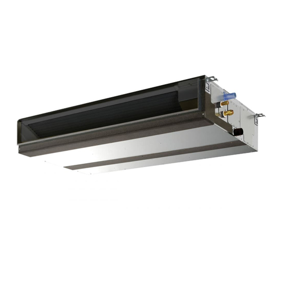
Ceiling concealed (Slim type) PEFY-WP-VMS1-E I.Ceiling concealed (Slim type) 1. SPECIFICATIONS............................1 - 4 2. EXTERNAL DIMENSIONS ..........................1 - 6 3. CENTER OF GRAVITY ........................... 1 - 8 4. ELECTRICAL WIRING DIAGRAMS ........................ 1 - 9 5. SOUND LEVELS ............................. 1 - 10 5-1. -
Page 7: Ceiling Concealed (Slim Type)
1. SPECIFICATIONS I.Ceiling concealed (Slim type) 1. SPECIFICATIONS Model PEFY-WP15VMS1-E PEFY-WP20VMS1-E PEFY-WP25VMS1-E PEFY-WP32VMS1-E 1-phase 220-230-240 V 50/60 1-phase 220-230-240 V 50/60 1-phase 220-230-240 V 50/60 1-phase 220-230-240 V 50/60 Power source Cooling capacity *1 kW (Nominal) *1 kcal/h 1,500 1,900 2,400 3,100 *1 BTU/h... - Page 8 1. SPECIFICATIONS Model PEFY-WP40VMS1-E PEFY-WP50VMS1-E 1-phase 220-230-240 V 50/60 1-phase 220-230-240 V 50/60 Power source Cooling capacity *1 kW (Nominal) *1 kcal/h 3,900 4,800 *1 BTU/h 15,400 19,100 *2 Power input 0.090 0.090 *2 Current input 0.73 0.77 Heating capacity *3 kW (Nominal) *3 kcal/h...
- Page 9 2. EXTERNAL DIMENSIONS 2. EXTERNAL DIMENSIONS PEFY-WP15, 20, 25, 32, 40, 50VMS1-E Unit : mm INDOOR UNITS 1 - 6...
- Page 10 2. EXTERNAL DIMENSIONS PEFY-WP15, 20, 25, 32, 40, 50VMS1-E Unit : mm INDOOR UNITS 1 - 7...
- Page 11 3. CENTER OF GRAVITY 3. CENTER OF GRAVITY PEFY-WP15, 20, 25, 32, 40, 50VMS1-E A: Center of gravity (mm)[in] Model name 625 [24-5/8] 752 [29-5/8] 263 [10-3/8] 338 [13-5/16] 105 [4-5/32] PEFY-WP15VMS1-E 625 [24-5/8] 752 [29-5/8] 263 [10-3/8] 338 [13-5/16] 105 [4-5/32] PEFY-WP20VMS1-E 625 [24-5/8]...
- Page 12 4. ELECTRICAL WIRING DIAGRAMS 4. ELECTRICAL WIRING DIAGRAMS PEFY-WP15, 20, 25, 32, 40, 50VMS1-E INDOOR UNITS 1 - 9...
- Page 13 5. SOUND LEVELS 5-1. Sound levels 5. SOUND LEVELS PEFY-WP-VMS1-E Sound level at anechoic room : Low-Mid-High Sound level dB ( A ) 15Pa 35Pa 50Pa Aux.duct PEFY-WP15VMS1-E 220-240V 22 - 24 - 26 22 - 24 - 28 23 - 26 - 29 23 - 27 - 30 PEFY-WP20VMS1-E 220-240V 22 - 25 - 28 23 - 25 - 29 24 - 27 - 30 25 - 28 - 32 PEFY-WP25VMS1-E 220-240V 22 - 25 - 29 23 - 26 - 30 24 - 28 - 31 25 - 29 - 33 PEFY-WP32VMS1-E 220-240V 26 - 28 - 30 28 - 30 - 33 30 - 32- 35 31 - 33 - 36...
- Page 14 5. SOUND LEVELS 5-2. NC curves PEFY-WP15VMS1-E PEFY-WP15VMS1-E PEFY-WP15VMS1-E External static pressure : 5Pa External static pressure : 15Pa External static pressure : 35Pa Power source : 220,230,240V, 50/60Hz Power source : 220,230,240V, 50/60Hz Power source : 220,230,240V, 50/60HzHz High speed High speed High speed Middle speed...
- Page 15 5. SOUND LEVELS PEFY-WP32VMS1-E PEFY-WP32VMS1-E PEFY-WP32VMS1-E External static pressure : 5Pa External static pressure : 15Pa External static pressure : 35Pa Power source : 220,230,240V, 50/60Hz Power source : 220,230,240V, 50/60Hz Power source : 220,230,240V, 50/60Hz High speed High speed High speed Middle speed Middle speed...
- Page 16 6. FAN CHARACTERISTICS CURVES 6. FAN CHARACTERISTICS CURVES PEFY-WP15VMS1-E PEFY-WP15VMS1-E External static pressure : 5Pa Suction : Back inlet External static pressure : 15Pa Suction : Back inlet Power source : 220,230,240V, 50/60Hz Power source : 220,230,240V, 50/60Hz Limit Limit High Middle High...
- Page 17 6. FAN CHARACTERISTICS CURVES PEFY-WP20VMS1-E PEFY-WP20VMS1-E Suction : Back inlet Suction : Back inlet External static pressure : 35Pa External static pressure : 50Pa Power source : 220,230,240V, 50/60Hz Power source : 220,230,240V, 50/60Hz Limit Limit High High Middle Middle Airflow rate (m /min) Airflow rate (m...
- Page 18 6. FAN CHARACTERISTICS CURVES PEFY-WP32VMS1-E PEFY-WP32VMS1-E Suction : Back inlet Suction : Back inlet External static pressure : 5Pa External static pressure : 15Pa Power source : 220,230,240V, 50/60Hz Power source : 220,230,240V, 50/60Hz Limit Limit High Middle High Middle Airflow rate (m /min) Airflow rate (m...
- Page 19 6. FAN CHARACTERISTICS CURVES PEFY-WP40VMS1-E PEFY-WP40VMS1-E Suction : Back inlet Suction : Back inlet External static pressure : 35Pa External static pressure : 50Pa Power source : 220,230,240V, 50/60Hz Power source : 220,230,240V, 50/60Hz Limit Limit High High Middle Middle Airflow rate (m /min) Airflow rate (m...
- Page 20 7. OPTIONAL PARTS 7-1. Optional parts line up for the Indoor unit 7. OPTIONAL PARTS Control box replace kit PEFY-WP15, 20, 25, 32, 40, 50VMS1-E PAC-KE70HS-E PEFY-WP-VMS1-E Control box replace kit PAC-KE70HS-E INDOOR UNITS 1 - 17...
- Page 21 7. OPTIONAL PARTS 7-2. Control box replace kit PAC-KE70HS-E Parts PLATE A PLATE B PLATE C COVER A Q'ty Shape Parts COVER B LEAD WIRE MOTOR LEAD WIRE LEV LEAD WIRE THM A Q'ty Shape White 7-pin connector White 6-pin connector White 4-pin connector Parts LEAD WIRE THM B...
-
Page 22: Ceiling Concealed (Middle Static Pressure Type)
Ceiling concealed (Middle static pressure type) PEFY-WP-VMA-E I.Ceiling concealed (Middle static pressure type) 1. SPECIFICATIONS............................1 - 20 2. EXTERNAL DIMENSIONS ..........................1 - 22 3. CENTER OF GRAVITY ........................... 1 - 24 4. ELECTRICAL WIRING DIAGRAMS ........................ 1 - 25 5. -
Page 23: Ceiling Concealed (Middle Static Pressure Type)
1. SPECIFICATIONS I.Ceiling concealed (Middle static pressure type) 1. SPECIFICATIONS Model PEFY-WP20VMA-E PEFY-WP25VMA-E PEFY-WP32VMA-E PEFY-WP40VMA-E 1-phase 220-230-240 V 50/ 1-phase 220-230-240 V 50/ 1-phase 220-230-240 V 50/ 1-phase 220-230-240 V 50/ Power source 60 Hz 60 Hz 60 Hz 60 Hz Cooling capacity *1 kW (Nominal) - Page 24 1. SPECIFICATIONS Model PEFY-WP50VMA-E 1-phase 220-230-240 V 50/ Power source 60 Hz Cooling capacity *1 kW (Nominal) *1 kcal/h 4,800 *1 BTU/h 19,100 *2 Power input 0.14 *2 Current input 1.15 Heating capacity *3 kW (Nominal) *3 kcal/h 5,400 *3 BTU/h 21,500 *2 Power input 0.12...
- Page 25 2. EXTERNAL DIMENSIONS 2. EXTERNAL DIMENSIONS PEFY-WP20, 25, 32, 40, 50VMA-E Unit : mm INDOOR UNITS 1 - 22...
- Page 26 2. EXTERNAL DIMENSIONS PEFY-WP20, 25, 32, 40, 50VMA-E Unit : mm INDOOR UNITS 1 - 23...
- Page 27 3. CENTER OF GRAVITY 3. CENTER OF GRAVITY PEFY-WP20, 25, 32, 40, 50VMA-E A : Center of gravity (mm)[in] Model name PEFY-WP20VMA-E 643 [25 - 6/16] 754 [29 - 11/16] 330 [13] 300 [11 -13/16] 130 [5 -2/16] PEFY-WP25VMA-E 643 [25 - 6/16] 954 [37 - 9/16] 375 [14 -13/16] 130 [5 -2/16]...
- Page 28 4. ELECTRICAL WIRING DIAGRAMS 4. ELECTRICAL WIRING DIAGRAMS PEFY-WP20, 25, 32, 40, 50VMA-E INDOOR UNITS 1 - 25...
- Page 29 5. SOUND LEVELS 5-1. Sound levels 5. SOUND LEVELS 5-1-1. Sound levels (Measured condition : With 1m air inlet duct and 2m air outlet duct) Sound level at anechoic room : Low-Mid-High PEFY-WP-VMA-E Model Sound level dB(A) 35Pa 50Pa 70Pa 100Pa 150Pa Aux.
- Page 30 5. SOUND LEVELS 5-2. NC curves 5-2-1. NC curves (Sound level measured condition : With 1m air inlet duct and 2m air outlet duct) PEFY-WP20VMA-E PEFY-WP20VMA-E PEFY-WP20VMA-E External Static Pressure: 35Pa External Static Pressure: 50Pa External Static Pressure: 70Pa Power Source: 220-240V(50/60Hz) Power Source: 220-240V(50/60Hz) Power Source: 220-240V(50/60Hz) 70.0...
- Page 31 5. SOUND LEVELS PEFY-WP32VMA-E PEFY-WP32VMA-E PEFY-WP32VMA-E External Static Pressure: 70Pa External Static Pressure: 100Pa External Static Pressure: 150Pa Power Source: 220-240V(50/60Hz) Power Source: 220-240V(50/60Hz) Power Source: 220-240V(50/60Hz) 70.0 70.0 70.0 50/60Hz 50/60Hz 50/60Hz High High High Middle 50/60Hz Middle 50/60Hz Middle 50/60Hz 65.0 65.0...
- Page 32 5. SOUND LEVELS 5-2-2. NC curves (Sound level measured condition : With 2m air inlet duct and 2m air outlet duct) PEFY-WP20VMA-E PEFY-WP20VMA-E PEFY-WP20VMA-E External Static Pressure: 35Pa External Static Pressure: 50Pa External Static Pressure: 70Pa Power Source: 220-230-240V(50/60Hz) Power Source: 220-230-240V(50/60Hz) Power Source: 220-230-240V(50/60Hz) 70.0 70.0...
- Page 33 5. SOUND LEVELS PEFY-WP32VMA-E PEFY-WP32VMA-E PEFY-WP32VMA-E External Static Pressure: 70Pa External Static Pressure: 100Pa External Static Pressure: 150Pa Power Source: 220-230-240V(50/60Hz) Power Source: 220-230-240V(50/60Hz) Power Source: 220-230-240V(50/60Hz) 70.0 70.0 70.0 50/60Hz 50/60Hz 50/60Hz High High High Middle 50/60Hz Middle 50/60Hz Middle 50/60Hz 65.0 65.0...
- Page 34 6. FAN CHARACTERISTICS CURVES 6. FAN CHARACTERISTICS CURVES PEFY-WP20VMA-E PEFY-WP20VMA-E External static pressure : 35Pa External static pressure : 50Pa Power source : 220-240V Power source : 220-240V Limit Limit High High Middle Middle Airflow rate (m /min) Airflow rate (m /min) PEFY-WP20VMA-E PEFY-WP20VMA-E...
- Page 35 6. FAN CHARACTERISTICS CURVES PEFY-WP25VMA-E PEFY-WP25VMA-E External static pressure : 35Pa External static pressure : 50Pa Power source : 220-240V Power source : 220-240V Limit Limit High High Middle Middle Airflow rate (m /min) Airflow rate (m /min) PEFY-WP25VMA-E PEFY-WP25VMA-E External static pressure : 70Pa External static pressure : 100Pa Power source : 220-240V...
- Page 36 6. FAN CHARACTERISTICS CURVES PEFY-WP32VMA-E PEFY-WP32VMA-E External static pressure : 35Pa External static pressure : 50Pa Power source : 220-240V Power source : 220-240V Limit Limit High High Middle Middle Airflow rate (m /min) Airflow rate (m /min) PEFY-WP32VMA-E PEFY-WP32VMA-E External static pressure : 70Pa External static pressure : 100Pa Power source : 220-240V...
- Page 37 6. FAN CHARACTERISTICS CURVES PEFY-WP40,50VMA-E PEFY-WP40,50VMA-E External static pressure : 35Pa External static pressure : 50Pa Power source : 220-240V Power source : 220-240V Limit Limit High High Middle Middle Airflow rate (m /min) Airflow rate (m /min) PEFY-WP40,50VMA-E PEFY-WP40,50VMA-E External static pressure : 70Pa External static pressure : 100Pa Power source : 220-240V...
- Page 38 7. OPTIONAL PARTS 7-1. Optional parts line up for the Indoor unit 7. OPTIONAL PARTS Filter box PEFY-WP20VMA-E PAC-KE91TB-E PEFY-WP25, 32VMA-E PAC-KE92TB-E PEFY-WP40, 50VMA-E PAC-KE93TB-E PEFY-WP-VMA-E PEFY-WP-VMA-E Filter box PAC-KE·TB-E 7-2. Filter box PAC-KE-TB-E Item Screw Filter box FLANGE Installation manual Quantity Shape Detailed installation information should be referred to its Installation Manual (...
- Page 39 INDOOR UNITS 1 - 36...
-
Page 40: Floor Standing (Concealed Type)
Floor standing (Concealed type) PFFY-WP-VLRMM-E I.Floor standing (Concealed type) 1. SPECIFICATIONS............................1 - 38 2. EXTERNAL DIMENSIONS ..........................1 - 40 3. CENTER OF GRAVITY ........................... 1 - 41 4. ELECTRICAL WIRING DIAGRAMS ........................ 1 - 42 5. SOUND LEVELS ............................. 1 - 43 5-1. -
Page 41: Cmb-Wp-V-G
1. SPECIFICATIONS I.Floor standing (Concealed type) 1. SPECIFICATIONS Model PFFY-WP20VLRMM-E PFFY-WP25VLRMM-E PFFY-WP32VLRMM-E PFFY-WP40VLRMM-E 1-phase 220-230-240 V 50/60 1-phase 220-230-240 V 50/60 1-phase 220-230-240 V 50/60 1-phase 220-230-240 V 50/60 Power source Cooling capacity *1 kW (Nominal) *1 kcal/h 1,900 2,400 3,100 3,900 *1 BTU/h... - Page 42 1. SPECIFICATIONS Model PFFY-WP50VLRMM-E 1-phase 220-230-240 V 50/60 Power source Cooling capacity *1 kW (Nominal) *1 kcal/h 4,800 *1 BTU/h 19,100 *2 Power input 0.070 *2 Current input 0.65 Heating capacity *3 kW (Nominal) *3 kcal/h 5,400 *3 BTU/h 21,500 *2 Power input 0.070 *2 Current input...
-
Page 43: External Dimensions
2. EXTERNAL DIMENSIONS 2. EXTERNAL DIMENSIONS PFFY-WP20, 25, 32, 40, 50VLRMM-E Unit : mm INDOOR UNITS 1 - 40... -
Page 44: Center Of Gravity
3. CENTER OF GRAVITY 3. CENTER OF GRAVITY PFFY-WP20, 25, 32, 40, 50VLRMM-E Floor hole for fixing (mm)[in] Model name 335 [13-1/4] [25-1/4] [3-15/16] PFFY-WP20VLRMM-E 17 [11/16] [29-15/16] [3-15/16] 335 [13-1/4] PFFY-WP25VLRMM-E 17 [11/16] [3-15/16] [29-15/16] 17 [11/16] 335 [13-1/4] PFFY-WP32VLRMM-E [3-15/16] 335 [13-1/4]... -
Page 45: Electrical Wiring Diagrams
4. ELECTRICAL WIRING DIAGRAMS 4. ELECTRICAL WIRING DIAGRAMS PFFY-WP20, 25, 32, 40, 50VLRMM-E INDOOR UNITS 1 - 42... -
Page 46: Sound Levels
5. SOUND LEVELS 5-1. Sound levels 5. SOUND LEVELS PFFY-WP-VLRMM-E Sound level at anechoic room : Low-Middle-High Sound level dB (A) Aux. duct 20Pa 40Pa 60Pa PFFY-WP20VLRMM-E 31-33-38 32-37-39 36-38-42 PFFY-WP25VLRMM-E 31-33-38 32-37-39 36-38-42 1.0m Measurement location PFFY-WP32VLRMM-E 31-35-38 34-37-40 36-40-42 PFFY-WP40VLRMM-E 34-37-40... -
Page 47: Sound Levels
5. SOUND LEVELS PFFY-WP40VLRMM-E PFFY-WP40VLRMM-E PFFY-WP40VLRMM-E External Static Pressure: 20Pa External Static Pressure: 40Pa External Static Pressure: 60Pa Power Source: 220-230-240V, 50/60Hz Power Source: 220-230-240V, 50/60Hz Power Source: 220-230-240V, 50/60Hz 70.0 70.0 70.0 50/60Hz 50/60Hz 50/60Hz High High High Middle 50/60Hz Middle 50/60Hz Middle 50/60Hz 65.0... -
Page 48: Fan Characteristics Curves
6. FAN CHARACTERISTICS CURVES 6. FAN CHARACTERISTICS CURVES PFFY-WP20VLRMM-E PFFY-WP20VLRMM-E External static pressure : 20Pa External static pressure : 40Pa Power source : 220-230-240V, 50/60Hz Power source : 220-230-240V, 50/60Hz Limit Limit High High Middle Middle Airflow rate (m /min) Airflow rate (m /min) PFFY-WP20VLRMM-E... - Page 49 6. FAN CHARACTERISTICS CURVES PFFY-WP32VLRMM-E PFFY-WP32VLRMM-E External static pressure : 20Pa External static pressure : 40Pa Power source : 220-230-240V, 50/60Hz Power source : 220-230-240V, 50/60Hz Limit Limit High High Middle Middle Airflow rate (m /min) Airflow rate (m /min) PFFY-WP32VLRMM-E PFFY-WP40VLRMM-E External static pressure : 60Pa...
- Page 50 6. FAN CHARACTERISTICS CURVES PFFY-WP50VLRMM-E PFFY-WP50VLRMM-E External static pressure : 20Pa External static pressure : 40Pa Power source : 220-230-240V, 50/60Hz Power source : 220-230-240V, 50/60Hz Limit Limit High High Middle Middle Airflow rate (m /min) Airflow rate (m /min) PFFY-WP50VLRMM-E External static pressure : 60Pa Power source : 220-230-240V, 50/60Hz...
- Page 51 INDOOR UNITS 1 - 48...
- Page 52 HBC controller CMB-WP-V-G I.HBC controller 1. SPECIFICATIONS............................1 - 50 2. EXTERNAL DIMENSIONS ..........................1 - 51 3. CENTER OF GRAVITY ........................... 1 - 53 4. ELECTRICAL WIRING DIAGRAMS ........................ 1 - 54 5. SOUND LEVELS ............................. 1 - 56 5-1.
-
Page 53: Optional Parts
1. SPECIFICATIONS I.HBC controller 1. SPECIFICATIONS Model name CMB-WP108V-G Number of branch Power source 220-230-240 V 50 Hz 60 Hz Power input Cooling 0.450/0.460/0.470 0.450/0.460/0.470 (220/230/240) Heating 0.450/0.460/0.470 0.450/0.460/0.470 Current input Cooling 2.89/2.83/2.79 2.89/2.83/2.79 (220/230/240) Heating 2.89/2.83/2.79 2.89/2.83/2.79 Sound pressure level (measured in anechoice room) dB ... -
Page 54: External Dimensions
2. EXTERNAL DIMENSIONS 2. EXTERNAL DIMENSIONS CMB-WP108V-G Unit : mm INDOOR UNITS 1 - 51... - Page 55 2. EXTERNAL DIMENSIONS CMB-WP108V-G with sub drainpan Unit : mm INDOOR UNITS 1 - 52...
-
Page 56: Center Of Gravity
3. CENTER OF GRAVITY 3. CENTER OF GRAVITY CMB-WP108V-G 1676 Center of gravity Indoor unit branching point INDOOR UNITS 1 - 53... -
Page 57: Electrical Wiring Diagrams
4. ELECTRICAL WIRING DIAGRAMS 4. ELECTRICAL WIRING DIAGRAMS CMB-WP108V-G INDOOR UNITS 1 - 54... - Page 58 4. ELECTRICAL WIRING DIAGRAMS CMB-WP108V-G (Detail of X section) INDOOR UNITS 1 - 55...
-
Page 59: Sound Levels
5. SOUND LEVELS 5-1. Sound levels 5. SOUND LEVELS (Measured point) CMB-WP108V-G Measurement location Measured in anechoic room. 5-2. NC curves CMB-WP108V-G External Static Pressure: 50Pa Power Source: 220-240V(50/60Hz) 70.0 65.0 60.0 NC-60 55.0 50.0 NC-50 45.0 40.0 NC-40 35.0 30.0 NC-30 25.0... -
Page 60: Optional Parts
6. OPTIONAL PARTS 6-1. Optional parts line up for the HBC controller 6. OPTIONAL PARTS Filter box CMB-WP108V-G PAC-HBC01DP-E 6-2. Sub drainpan PAC-HBC01DP-EDrain hose I.D.32(1-1/4")····································· 1pc. Hose band···························································· 1pc. Note1.This sub drainpan is an option only for HBC CONTROLLER. Any other use is not permitted. - Page 61 INDOOR UNITS 1 - 58...
- Page 62 CAPACITY TABLES Capacity Table I.CAPACITY TABLES 1. Cooling [Ceiling concealed (Slim type)] ......................1 - 60 1-1. Cooling capacity with PURY-WP200-250YJM-A ..................1 - 60 2. Cooling [Ceiling concealed (Middle static pressure type)] ................1 - 61 2-1. Cooling capacity with PURY-WP200-250YJM-A ..................1 - 61 3.
-
Page 63: Cooling [Ceiling Concealed (Slim Type)]
1. Cooling [Ceiling concealed (Slim type)] 1-1. Cooling capacity with PURY-WP200-250YJM-A I.CAPACITY TABLES 1. Cooling [Ceiling concealed (Slim type)] PEFY-WP-VMS1-E CA:Capacity(kW) , SHC:Sensible Heat Capacity(kW) Model Outdoor Indoor air temp. size air temp. 21.5°C D.B. 23°C D.B. 25°C D.B. 27°C D.B. 28°C D.B. -
Page 64: Cooling [Ceiling Concealed (Middle Static Pressure Type)]
2. Cooling [Ceiling concealed (Middle static pressure type)] 2-1. Cooling capacity with PURY-WP200-250YJM-A 2. Cooling [Ceiling concealed (Middle static pressure type)] PEFY-WP-VMA-E CA:Capacity(kW) , SHC:Sensible Heat Capacity(kW) Model Outdoor Indoor air temp. size air temp. 21.5°C D.B. 23°C D.B. 25°C D.B. 27°C D.B. -
Page 65: Cooling [Floor Standing (Concealed Type)]
3. Cooling [Floor standing (Concealed type)] 3-1. Cooling capacity with PURY-WP200-250YJM-A 3. Cooling [Floor standing (Concealed type)] PFFY-WP-VLRMM-E CA:Capacity(kW) , SHC:Sensible Heat Capacity(kW) Model Outdoor Indoor air temp. size air temp. 21.5°C D.B. 23°C D.B. 25°C D.B. 27°C D.B. 28°C D.B. 30°C D.B. -
Page 66: Heating [All Indoor Units]
4. Heating [All indoor units] 4-1. Heating capacity with PURY-WP200-250YJM-A 4. Heating [All indoor units] All Indoor units SHC:Sensible Heat Capacity(kW) Model Outdoor Indoor air temp. size air temp. 15°C D.B. 20°C D.B. 25°C D.B. 27°C D.B. (Rated kW) °C W.B. -20.0 -15.0 -10.0... -
Page 67: Heating Capacity With Pury-Wp200-250Yjm-A "Cop Priority Mode
4. Heating [All indoor units] 4-2. Heating capacity with PURY-WP200-250YJM-A "COP priority mode" All Indoor units SHC:Sensible Heat Capacity(kW) Model Outdoor Indoor air temp. size air temp. 15°C D.B. 20°C D.B. 25°C D.B. 27°C D.B. (Rated kW) °C W.B. -20.0 -15.0 -10.0 -5.0... - Page 68 HYBRID CITY MULTI 2. OUTDOOR UNITS HYBRID CITY MULTI ..........................2 - 3 OUTDOOR UNITS 2 - 1...
- Page 69 OUTDOOR UNITS 2 - 2...
- Page 70 HYBRID CITY MULTI OUTDOOR UNITS I.HYBRID CITY MULTI 1. SPECIFICATIONS............................2 - 4 2. EXTERNAL DIMENSIONS ..........................2 - 5 3. CENTER OF GRAVITY ........................... 2 - 7 4. ELECTRICAL WIRING DIAGRAMS ........................ 2 - 8 5. SOUND LEVELS ............................. 2 - 9 6.
-
Page 71: Specifications
0 Pa (0 mmH 0 Pa (0 mmH Compressor Type x Quantity Inverter scroll hermetic compressor Inverter scroll hermetic compressor Manufacture AC&R Works, MITSUBISHI ELECTRIC CORPORATION AC&R Works, MITSUBISHI ELECTRIC CORPORATION Starting method Inverter Inverter Motor output Case heater 0.045 (240 V) 0.045 (240 V) - Page 72 2. EXTERNAL DIMENSIONS 2. EXTERNAL DIMENSIONS PURY-WP200,250YJM-A Unit : mm OUTDOOR UNITS 2 - 5...
-
Page 73: External Dimensions
2. EXTERNAL DIMENSIONS PURY-WP200,250YJM-A Unit : mm OUTDOOR UNITS 2 - 6... -
Page 74: Center Of Gravity
3. CENTER OF GRAVITY 3. CENTER OF GRAVITY PURY-WP200, 250YJM-A 1220 Unit:mm Model PURY-WP200YJM-A PURY-WP250YJM-A 1060 OUTDOOR UNITS 2 - 7... -
Page 75: Electrical Wiring Diagrams
4. ELECTRICAL WIRING DIAGRAMS 4. ELECTRICAL WIRING DIAGRAMS PURY-WP200, 250YJM-A OUTDOOR UNITS 2 - 8... -
Page 76: Sound Levels
5. SOUND LEVELS 5. SOUND LEVELS Measurement condition PURY-WP200,250YJM-A Measurement location Sound level of PURY-WP200YJM-A Stand 50/60Hz 50/60Hz NC-70 NC-60 NC-50 NC-40 NC-30 Approximate minimum audible limit on NC-20 continuous noise Octave band central frequency (Hz) dB(A) Standard 50/60Hz 72.0 65.0 61.5 57.0 53.5 50.0 46.5 40.0 60.0... -
Page 77: Capacity Tables
6. CAPACITY TABLES 6-1. Correction by temperature 6. CAPACITY TABLES CITY MULTI could have various capacities at different designing temperatures. Using the nominal cooling/heating capacity values and the ratios below, the capacity can be found for various temperatures. PURY- WP200YJM-A WP250YJM-A Indoor Temperature Nominal 22.4... - Page 78 6. CAPACITY TABLES Correction by temperature (COP Priority Mode) CITY MULTI could have various capacities at different designing temperatures. Using the nominal cooling/heating capacity val- ues and the ratios below, the capacity can be found for various temperatures. To select COP priority mode, DipSW 3-7 must be set to ON. PURY- WP200YJM-A WP250YJM-A Indoor Temperature...
-
Page 79: Correction By Total Indoor
6. CAPACITY TABLES 6-2. Correction by total indoor CITY MULTI system have different capacities and inputs when many combinations of indoor units with different total capacities are connected. Using following tables, the maximum capacity can be found to ensure the system is installed with enough capacity for a particular application. -
Page 80: Correction By Piping Length
6. CAPACITY TABLES 6-3. Correction by piping length A decrease in cooling/heating capacity will occur due to piping length increase. Using the following correction factors according to the equivalent length of the piping shown at 6-3-1 and 6-3-2 the capacity can be calculated. 6-3-3 shows how to obtain the equiv- alent length of piping. - Page 81 6. CAPACITY TABLES 6-3-2. Heating capacity correction PURY-WP200YJM-A PURY-WP200YJM-A 1.00 0.99 0.98 0.95 0.97 0.96 0.90 0.95 0.94 0.85 0.93 HBC to outdoor unit refrigerant piping equivalent length (m) Water piping equivalent length to farthest indoor unit (m) PURY-WP250YJM-A PURY-WP250YJM-A 1.00 0.99 0.98...
-
Page 82: Correction At Frost And Defrost
6. CAPACITY TABLES 6-3-3. How to obtain the equivalent piping length Refrigerant pipe 1. PURY-WP200YJM-A Equivalent length = (Actual piping length to the farthest indoor unit) + (0.35 × number of bends in the piping) [m] 2. PURY-WP250YJM-A Equivalent length = (Actual piping length to the farthest indoor unit) + (0.42 × number of bends in the piping) [m] Water pipe 3. -
Page 83: Correction By Brine Concentration
6. CAPACITY TABLES 6-5. Correction by brine concentration In HYBRID CITY MULTI system, brine should be used to prevent the system from freezing. Refer to the following graphs for the capacity correction by brine.Refer to 6-5-1 for brine concentration, 6-5-2 and 6-5-3 for capacity correction by brine concentration. 6-5-1. -
Page 84: Operation Temperature Range
6. CAPACITY TABLES 6-6. Operation temperature range Outdoor temperature Outdoor temperature Combination of cooling/heating operation (Cooling main or Heating main) Indoor temperature Outdoor temperature Cooling Heating -5 to 21 CDB (23 to 70 FDB) 15 to 27 CDB (59 to 81 FDB) -6 to 15.5 CWB (21 to 60 FWB) 15 to 24 CWB (59 to 75 FWB) OUTDOOR UNITS... - Page 85 OUTDOOR UNITS 2 - 18...
- Page 86 HYBRID CITY MULTI 3. CONTROLLER 1. MITSUBISHI ELECTRIC's Air-conditioner Network System. (MELANS) ............3 - 2 1-1.Function table of controllers ........................3 - 3 2. Local remote controller ............................ 3 - 4 2-1.MA remote controller [PAR-31MAA]......................3 - 4 2-2.MA remote controller [PAR-21MAA]......................3 - 5 2-3.ME remote controller [PAR-F27MEA]......................
-
Page 87: Controller
1. MITSUBISHI ELECTRIC's Air-conditioner Network System. (MELANS) I. 1. MITSUBISHI ELECTRIC's Air-conditioner Network System. (MELANS) System Controller MITSUBISHI ELECTRIC's Air-conditioner Network System (MELANS) leads air conditioner management a PC browser and Network era. MELANS Use of our MELANS products enhances EFFICIENCY and QUALITY of air-conditioning, contributing to ENERGY SAVING and reduction in running cost. -
Page 88: Mitsubishi Electric's Air-Conditioner Network System. (Melans)
1. MITSUBISHI ELECTRIC's Air-conditioner Network System. (MELANS) 1-1. Function table of controllers Local remote controller System controller Model PAR- PAR- PAR- PAC- PAC- PAR- PAC- *4 *5 AG-150A + GB-50ADA TG-2000A AT-50A AG-150A 31MAA 21MAA F27MEA YT52CRA SE51CRA FL32MA YT40ANRA... - Page 89 2. Local remote controller 2-1. MA remote controller [PAR-31MAA] 2. Local remote controller 2. Schedule and timer setting :Each group :Not available Item Description Setting Display Timer ON/OFF timer Turns ON and OFF daily at a set time. • Time can be set in 5-minute increments. •...
-
Page 90: Local Remote Controller
2. Local remote controller 2-2. MA remote controller [PAR-21MAA] Functions :Each unit :Each group :Each block :Each floor :Collective :Not available Description Operations Display Item ON/OFF ON and OFF operation for a single group TIME SUN MON TUE WED THU FRI SAT TIMER AFTER AFTER... -
Page 91: 2-3.Me Remote Controller [Par-F27Mea]
2. Local remote controller 2-3. ME remote controller [PAR-F27MEA] Functions ON and OFF operation for a single group This remote control requires non-polar wiring to only one indoor unit. ON/OFF, Group operation over multiple outdoor units is possible. Grouping can be changed without re- wiring, which makes dividing rooms for tenant easier . -
Page 92: 2-4.Simple Ma Remote Controller [Pac-Yt52Cra]
2. Local remote controller 2-4. Simple MA remote controller [PAC-YT52CRA] Functions :Each unit :Each group :Each block :Each floor :Collective :Not available Description Operations Display Item Changes between ON and OFF. ON/OFF Operation mode Select from COOL, DRYING, FAN, AUTO, and HEAT. switching Sets a room temperature. -
Page 93: 2-5.Simple Me Remote Controller [Pac-Se51Cra]
2. Local remote controller 2-5. Simple ME remote controller [PAC-SE51CRA] Functions ON and OFF operation for a single group Control: ON/OFF, room temperature, fan speed. ON/OFF, The only wiring required is cross-over wiring based two-wire signal lines. Room temperature sensors are built-in. Ability to limit the set temperature by AG-150A/ GB-50A (upper and lower temperature can be set) -
Page 94: 2-6.Wireless Remote Controller [Par-Fl32Ma / Par-Fa32Ma]
2. Local remote controller 2-6. Wireless remote controller [PAR-FL32MA / PAR-FA32MA] Functions :Each unit :Each group :Each block :Each floor :Collective :Not available Description Operations Display Item ON/OFF ON and OFF operation for a single group ON/OFF Operation mode Switches between Cool / Dry / Fan / Heat / Auto. switching Operation modes vary depending on the air conditioner unit. -
Page 95: 2-7.Lossnay Remote Controller [Pz-52Sf]
2. Local remote controller 2-7. LOSSNAY remote controller [PZ-52SF] Functions :Each unit :Each group :Each block :Each floor :Collective :Not available Description Operations Display Item ON/OFF ON and OFF operation for a LOSSNAY unit CENTRAL INTERLOCKED Switches between automatic ventilation/ vent - heat HEAT EX. -
Page 96: 2-8.Lossnay Remote Controller For Lgh-Rx5-E [Pz-60Dr-E]
2. Local remote controller 2-8. LOSSNAY remote controller for LGH-RX5-E [PZ-60DR-E] Functions (in case of LGH-RX5-E) Function(Communicating mode) New Function Extra low fan speed (Except LGH-150RX and 200RX Weekly timer Simple timer Night Purge mode Multi languages display 24-hours ventilation (Except LGH-150RX and 200RX Operation function limit Clock display... -
Page 97: System Remote Controller
3. System remote controller 3-1. ON/OFF remote controller [PAC-YT40ANRA] 3. System remote controller Functions : Each unit : Each group : Each block : Each floor : Group or collective : Not available CENTRALIZED CENTRALIZED ON/OFF ON/OFF Description Operations Display Item ON/OFF ON and OFF operation for the air conditioner units... - Page 98 3. System remote controller System example ON/OFF remote HBC controller controller MA remote MA remote controller controller LOSSNAY LOSSNAY LOSSNAY LOSSNAY LOSSNAY remote remote controller controller External dimension Unit:mm[in.] (Front view) (Side view) 18.1 (Rear view) 130 [ ON/OFF ON/OFF CENTRALIZED CENTRALIZED 46 [...
-
Page 99: 3-2.Advanced Touch Controller [At-50A]
3. System remote controller 3-2. Advanced touch controller [AT-50A] :Each unit :Each group :Each block :Available Functions :Group or collective :Each floor :Not available Description Operations Display Item ON and OFF operation for the air conditioner units. The Batch Operation ON/OFF button will light up when one or more air ON/OFF conditioning units are operated. - Page 100 3. System remote controller System example (1) Connection with HYBRID CITY MULTI units M-NET M-NET Advanced touch controller AT-50A HBC controller LOSSNAY unit HYBRID Indoor unit CITY MULTI Power supply unit ME remote PAC-SC51KUA controller CONTROLLER 3 - 15...
- Page 101 3. System remote controller 1. Power supply to AT-50A AT-50A needs DC power supply of M-NET (24~32VDC) for centralized control transmission use, operation. (1). Power supply of M-NET from power supply unit PAC-SC51KUA. Power supply unit PAC-SC51KUA is recommended for AT-50A. See the diagram below ; for details, please refer to the installation manual of Power supply unit PAC-SC51KUA M-NET M-NET...
- Page 102 3. System remote controller (3) Power supply of M-NET from outdoor unit connector TB3. AT-50A can also receive power supply from R410A/R407C/ R22 outdoor unit connector TB3. However, if the outdoor unit shuts down, AT-50A will also automatically shut down. Therefore, this scheme is not recommended for air conditioning system consisting of multiple outdoor units.
- Page 103 3. System remote controller 2. External input/output usage External input connector External output connector (1). External signal input function External signal input requires the external I/O adapter (Model: PAC-YT41HAA) sold separately. 1). External input External no-voltage contact signal can be used to send signals indicating the following status of all air conditioning units that are controlled : Emergency stop/Normal, ON/OFF, and local remote controller operation Prohibit/Permit.
- Page 104 3. System remote controller Recommended circuit example (A) For level signal Green Yellow ON/OFF or Emergency stop Max. 10 m This unit (32ft) (B) For pulse signal Green Yellow Orange Brown Prohibit Max. Enable Stop 10 m This unit (32ft) The relays and extension cables, etc.
- Page 105 3. System remote controller 3. Screens of AT-50A GRID (S) GRID (L) LIST GROUP Status List System-Changeover CONTROLLER 3 - 20...
- Page 106 3. System remote controller Prohibit Remote Controller Operation Lock Set Temperature Range Limit Set Schedule Display Format CONTROLLER 3 - 21...
-
Page 107: 3-3.Centralized Controller [Ag-150A]
3. System remote controller 3-3. Centralized controller [AG-150A] Functions :Each unit :Each group :Each block :Each floor :Collective :Not available Description Operations Display Item ON and OFF operation for the air conditioner units ON/OFF Switches between Cool / Dry / Auto / Fan / Heat. (Group of LOSSNAY unit : Operation mode automatic ventilation/ vent - heat interchange/ normal ventilation) switching... - Page 108 3. System remote controller 1. Power supply to AG-150A AG-150A needs DC power supply of 24V and M-NET (24~32V); the former is for centralized control transmission use and the latter is for AG-150A's operating and LAN function use. (1). Power supply unit PAC-SC51KUA is the recommended power supplier for AG-150A. The basic scheme is as follows. For details, please refer to Power supply unit PAC-SC51KUA.
- Page 109 3. System remote controller 2. External input/output usage NOTE : When using the AG-150A connected with the expansion controller, use external input/output function of the expansion controller. (1). External signal input function To use the external signal input, an external I/O adapter (PAC-YG10HA; sold separately) and an external power supply are required. 1).
- Page 110 3. System remote controller Recommended circuit example (A) For level signal ON/OFF or Emergency stop Orange Power supply(*1) (12VDC or 24VDC) Use relays X1, X2, Y1, and Y2 that meet the Max.10m following specifications. (32 ft) Contact rating This unit Rated voltage >= 12VDC (B) For pulse signal...
- Page 111 3. System remote controller 3. LAN connection function When using the LAN connection function, connect the LAN cable to the LAN connector of this device. Procure the LAN cable at the site, and use 100 BASE-TX Straight cable. For a description of the IP address setting method, refer to Instruction Book. LAN is 100 BASE-TX Specification.
- Page 112 3. System remote controller 4. Browser screens of AG-150A Condition List (Overview) Condition List (Block) Condition List (Overview/Floor Layout) peration Malfunction List Malfunction Log CONTROLLER 3 - 27...
- Page 113 3. System remote controller Weekly 1 Schedule Weekly 1 Schedule (Setting screen) Measurement status monitor (temperature Operation (DIDO Controller) sensor/humidity sensor /measurement meter) Trend Graph (temperature/humidity) Trend Graph (Peak cut control) CONTROLLER 3 - 28...
- Page 114 3. System remote controller 5. Liquid crystal displays of AG-150A Floor screen Floor screen (Zoom-out display) Floor layout screen Floor layout screen (Zoom-out display) Weekly schedule setting screen Annual schedule setting screen Block display screen Operation screen CONTROLLER 3 - 29...
- Page 115 3. System remote controller Error status screen Error history display screen 6. Option Model Description PAC-YG81TB Mounting attachment B type for AG-150A wall-mount installations PAC-YG83UTB Electric box for AG-150A wall-embed installations PAC-YG85KTB Mounting attachment A type for AG-150A/PAC-SC51KUA wall-mount installations PAC-YG71CBL Black surface cover for AG-150A External input/output adapter for AG-150A/GB-50ADA/PAC-YG50ECA...
-
Page 116: 3-4.Centralized Controller [Gb-50Ada-J]
3. System remote controller 3-4. Centralized controller [GB-50ADA-J] *GB-50ADA-J is indicated as GB-50ADA. Functions :Each unit :Each group :Each block :Each floor :Collective :Not available Item Description Operations Display ON/OFF Run and stop operation for the air conditioner units Operation mode Switches between Cool / Dry / Auto / Fan / Heat. - Page 117 3. System remote controller 1. M-NET power supply GB-50ADA has a built-in function to supply power to the M-NET transmission line. (power supply coefficient: 6) When power is supplied from GB-50ADA, the types of system controllers listed in the table below are connectable. System controller M-NET remote controller System remote controller...
- Page 118 3. System remote controller 3. External input/output usage (1). External signal input function * To use the external signal input, a separately-sold external input/output adapter (PAC-YG10HA) and external power supply are required. External input/output terminal (CN5) MODEL : Serial number : 1).
- Page 119 3. System remote controller (B) Pulse signals If pulse signals to operate the units are received while the units are in operation, the units will continue their operation (same with the Stop, Prohibit, and Permit signals). When operation from the local remote controllers is prohibited, Run/Stop mode, operation mode, temperature setting, and filter reset settings cannot be changed from the local remote controller.
- Page 120 3. System remote controller 4. LAN connection function Connect the LAN cable to the LAN connector of this device. Procure the LAN cab le at the site, and use an enhanced category 5 UTP cable. For a description of the IP address setting method, refer to Installation Manual. LAN is 100 BASE-TX Specification.
- Page 121 3. System remote controller 5. Browser screens of GB-50ADA Condition List (Overview) Condition List (Block) Operation Malfunction List Malfunction Log Weekly Schedule CONTROLLER 3 - 36...
- Page 122 3. System remote controller Measurement status monitor (temperature Operation (DIDO Controller) sensor/humidity sensor /measurement meter) Trend Graph (temperature/humidity) Trend Graph (Peak cut control) CONTROLLER 3 - 37...
- Page 123 3. System remote controller 3-5. Power supply unit [PAC-SC51KUA] PAC-SC51KUA supplies DC power of M-NET (22-30V) and 24V at TB2 and TB3 respectively; the former is for centralized transmission use and the latter is for AG-150A operation and LAN function use. 1.
- Page 124 3. System remote controller 2. When supply power to 1 AG-150A, the PAC-SC51KUA can supply power to other system controllers as follows. Table3 Connectable number of system controller when 1 AG-150A is used. V : Connectable Total number of ON/OFF remote controller(AN) When connected to one AG-150A Total number of System remote controller(SR)
- Page 125 3. System remote controller External dimension Unit:mm[in.] 271 ( 10- 11 72 ( 2- 7 16 ) 90 ( 3- 9 16 ) This device complies with Part15 of the FCCRules.Operation is subject to the following two conditions:(1)this device may not cause harmful interference,and(2)this device must accept any interference received,including interference that may cause undesired operation.
-
Page 126: 3-6.Expansion Controller [Pac-Yg50Eca]
3. System remote controller 3-6. Expansion Controller [PAC-YG50ECA] PAC-YG50ECA can enhance units that AG-150A can control up to 150 by connecting 3 Expansion Controller (PAC-YG50ECA). PAC-YG50ECA has a built-in function to supply power to the M-NET transmission line. (power supply coefficient:6) 1.Specifisations Items Specifications... - Page 127 3. System remote controller 3.M-NET power supply PAC-YG50ECA has a built-in function to supply power to the M-NET transmission line. (power supply coefficient:6) When power is supplied from PAC-YG50ECA , the types of system controllers listed in the table below are connectable. System controller M-NET remote controller System remote controller...
- Page 128 3. System remote controller 5.System configuration Do not connect directly to the Internet. When connecting to the Internet through the AG-150A etc., use a security device such as a VPN router. Each unit can control up to a total of 2000 indoor, LOSSNAY, and other units. PC for centralized control M-NET (TG-2000A)
-
Page 129: 3-7.Integrated Centralized Control Software [Tg-2000A]
3. System remote controller 3-7. Integrated centralized control software [TG-2000A] 1. Example of Basic System Configuration. Single-phase 208/230V M-NET CENTRALIZED CONTROLLER AG-150A monitor Input AG-150A license controller Schedule 24VDC license Single-phase 208/230V Energy manag- Power supply unit ement PAC-SC51KUA controller etc. - Page 130 3. System remote controller 2. List of TG-2000A functions (1). The data for each AG-150A/GB-50ADA can be grouped and used to control the operation of up to 2000 units in floor or block units,etc., from the personal computer screen. By using a PI Controller/PLC or a watt-hour meter, the power rate can be apportioned, energy saving control can be executed, and other general equipment can be controlled.
- Page 131 3. System remote controller 3. Screens of TG-2000A Weekly schedule screen Floor screen Annual schedule screen Block screen All floor screen Operation setting screen Air-conditioning charge screen CONTROLLER 3 - 46...
- Page 132 3. System remote controller 4. Requirements (system recommendations) We recommend the following software and hardware when using this application (TG-2000A). TG-2000A version System Requirements When AG-150A(GB-50ADA)/G-50A-compatible OS : Windows7 *4/Vista/XP TG-2000A Ver.5.50 or later *1 *2 *3 Refer to the table below for details. TG-2000A is used When G-50A-compatible TG-2000A OS : Windows XP/2000...
-
Page 133: Compatible Units
3. System remote controller 5. Compatible Units The TG-2000A has two main functions: centralized control of air conditioners and cost accounting. However, not all functions are available with all air conditioners. Table: Compatible units and function list ( : supported, : Certain restrictions apply, : Not supported) Function... -
Page 134: 3-8.Plc Software For General Equipment [Pac-Yg21Cda]
3. System remote controller 3-8. PLC software for general equipment [PAC-YG21CDA] MITSUBISHI ELECTRIC's Air Conditioner control system can combine control of general equipment like lighting, air condition- ers from other manufacturers, etc. Functions on general equipment : On/Off operation, alarm, monitoring, scheduling. -
Page 135: 3-9.Bacnet ® Interface [Bac-Hd150]
3. System remote controller ® 3-9. BACnet interface [BAC-HD150] ® HYBRID CITY MULTI can easily combine into a Building Management System (BMS) via the BACnet and M-NET adapter ® BAC-HD150. BACnet is an opened transmission protocol widely used at BMS, and related equipment control. ®... - Page 136 3. System remote controller System example (Connection of 50 units / groups) Central monitor ® BACnet /IP LAN1 M-NET M-NET HBC controller BAC-HD150 ® BACnet /IP ME remote ME remote controller controller M-NET HBC controller LOSSNAY unit * When using the dual set point function, a maximum of 50 units can be connected.
-
Page 137: 3-10.Plc Software For Demand Input [Pac-Yg41Cda]
3. System remote controller 3-10. PLC software for demand input [PAC-YG41CDA] MITSUBISHI ELECTRIC's HYBRID CITY MULTI has its intelligent way to carry out peak-cut control while maximizing the air conditioning effect. System example The registration of - Energy saving setting... - Page 138 3. System remote controller Applying the energy saving setting from the integrated centralized control software TG-2000A or Initial setting Web allows conducting the energy saving control by the indoor/outdoor units or peak-cut control by using PLC. Item Content Energy saving Indoor unit control The TG-2000A or Initial setting Web sets the f ollowing energy saving items and energy saving control...
-
Page 139: On Orks Interface [Lmap04-E]
3. System remote controller ORKS ® 3-11. L interface [LMAP04-E] ® HYBRID CITY MULTI can easily combine into a Building Management System (BMS) via the and M-NET adapter ORKS LMAP04-E. ® is an opened transmission protocol widely used at BMS, and related equipment control. ORKS HYBRID CITY MULTI is therefore compatible with large-scaled BMS management via ®... - Page 140 3. System remote controller Environment specification Item Description Connected Equipment MITSUBISHI ELECTRIC Multiple split-type air conditioners HYBRID CITY MULTI Heat recovery ventilators LOSSNAY ( For details of the connectable models,please contact the dealer.) Number of Units LM-AP can control 50 indoor units (including LOSSNAY)
- Page 141 3. System remote controller External dimension Unit: mm [in.] 360 [14-3/16] 59.6 [2-3/8] 240 [9-1/2] 60 [2-3/8] 9.6 [3/8] Detail of A section 4.5 [ Item Description 340 (H) x 360 (W) x 59.6 (D) Dimensions [13- (H) x 14- (W) x 2- (D)] Net Weight...
- Page 142 3. System remote controller 3-12. Transmission booster [PAC-SF46EPA] The Outdoor unit supplies transmission power 30VDC for the indoor-outdoor transmission line at its connector TB3 and TB7. The power is consumed by the Indoor unit, ME remote controller, Timers and System controllers.When the total quantity of Indoor units, ME remote controller, Timers, and System controllers is over 40, or when transmission power supply is not enough, the transmission booster PAC-SF46EPA should be designed into the air-conditioner system to ensure the system communication.
- Page 143 Unit: mm (in) Usage Restrictions • Mitsubishi Electric does not take financial responsibility for damages caused by issues beyond our control or special circumstances (predicable or unpredictable); and secondary or accidental damages, and damages to other objects. We also do not take financial responsibility for opportunities lost as a result of device failure, or electrical power failure at the end-user site.
- Page 144 3. System remote controller 1. Specifications (1). Device Specifications Item Rating and Specification Power Supply 24 VDC 10%: 5 W Screw terminal block (M3) (*3) M-NET communication 17 to 30 VDC (*1) Screw terminal block (M3) (*3) Number of contacts: 4 Pulse signal: a-contact Pulse width:...
- Page 145 3. System remote controller • For the shield ground of the M-NET centralized control line for central control, use single-point grounding at the power unit for the transmission line. However, when supplying electric power to the M-NET centralized control line from the R410A series outdoor unit without using a power supply unit for the transmission line, use single-point grounding at the TB7 of that outdoor unit.
- Page 146 3. System remote controller (2). Parts Purchased Separately Prepare the following parts to install this device. Required Part Specification Unit fixing screws M4 screw × 4 (* M4: ISO metric screw thread) Power source: 24 VDC 0.2 A (Mini mum loading), SELV circuit, power line with grounding terminal Ripple noise: Lower than 200 mVp-p Compatible specification Power supply for this...
- Page 147 3. System remote controller 2. Wiring Instructions (1). Connecting the Power and M-NET Transmission Lines Tightening torque for terminal screws: 1 N·m Connect the M-NET transmission line of this device to a power supply unit (PAC-SC51KUA) for the transmission line or an outdoor unit (either a centralized control line or indoor control line can be CN17 connected).
- Page 148 3. System remote controller (2). Connecting the Signal Lines • Separately procure items such as terminal blocks and cables locally. • The maximum wire length is 100 m (328 ft). However, since the use of long wires makes the device susceptible to noise, using wires shorter than 10 m (32.8 ft) is recommended. 1) Pulse input (non-voltage a-contact) Device side 24 VDC...
- Page 149 Unit: mm (in) Usage Restrictions • Mitsubishi Electric does not take financial responsibility for damages caused by issues beyond our control or special circumstances (predicable or unpredictable); and secondary or accidental damages, and damages to other objects. We also do not take financial responsibility for opportunities lost as a result of device failure, or electrical power failure at the end-user site.
- Page 150 3. System remote controller 1. Specifications (1). Device Specifications Item Rating and Specification Screw terminal block Power Supply 24 VDC 10%: 5 W (*1) (M3) (*8) Screw terminal block M-NET communication 17 to 30 VDC (*2) (M3) (*8) Applied load MAX: 24 VDC, 5 W Screw terminal block Non-voltage Relay contact (2)
- Page 151 3. System remote controller Centralized control line Power supply unit PAC-SC51KUA M-NET M-NET Indoor control line 24 VDC DIDO controller Power supply CENTRALIZED CONTROLLER AG-150A AG-150A HBC controller HYBRID CITY MULTI (GB-50ADA) (a) (b) Ventilation fan, × up to 6 units lighting, etc.
- Page 152 3. System remote controller (2). Parts Purchased Separately Prepare the following parts to install this device. Required Part Specification Unit fixing screws M4 screw 4 (*M4: ISO metric screw thread) Commercially available power source: 24 VDC 10% 0.2 A (Minimum loading), SELV circuit, power line with grounding terminal Ripple noise: Lower than 200 mVp-p Compatible specification...
- Page 153 3. System remote controller 2. Wiring Instructions (1). Connecting the Power and M-NET Transmission Lines Tightening torque for terminal screws: 1 N·m Connect the M-NET transmission line of this device to a power supply unit (PAC-SC51KUA) for the M-NET transmission line or an outdoor unit (either a centralized control line or indoor CN17 CN16...
- Page 154 3. System remote controller (2). Connecting the Signal Lines • Separately procure the relay, power supply for the relay, terminal block, and cable locally. • The maximum wire length is 100 m (328 ft). However, since the use of long wires makes the device susceptible to noise, using wires shorter than 10 m (32.8 ft) is recommended.
- Page 155 3. System remote controller (1-2) Output Non-voltage Relay contact or transistor is available for output. Only one can be used at a time. (a) Non-voltage Relay Contact Outputs Operate (ON) output : Contacts closed Power supply Load Stop (OFF) output : V1 (DC) Contacts open Power supply...
- Page 156 3. System remote controller (b) Transistor Outputs (Open Collector) 24 VDC Operate (ON) output : Power source Transistor ON (sink) Stop (OFF) output : Transistor OFF (open) Field *Upon pulse output, the Connections (ON),(OFF) transistors turn ON (sink) according to the output content.
- Page 157 3. System remote controller 2) Expansion Connectors (Channels 3 to 6) (2-1) Expansion Inputs/Outputs Purchase an optional external input/output adapter (model: PAC-YG10HA) when using expansion inputs/outputs. PAC-YG66DCA has two expansion connectors, and up to two external input/output devices can be connected to each connector. An optional external input/output adapter is required for each connector used.
- Page 158 3. System remote controller 3. Interlock control The DIDO controller (PAC-YG66DCA) has an interlock control function, which enables operation or set temperature change on the M-NET devices such as indoor units and also enables signal output to the contacts on the DIDO controller. Interlock control covers the units connected to the DIDO controller with M-NET system.
- Page 159 Unit: mm (in) Usage Restrictions • Mitsubishi Electric does not take financial responsibility for damages caused by issues beyond our control or special circumstances (predicable or unpredictable); and secondary or accidental damages, and damages to other objects. We also do not take financial responsibility for opportunities lost as a result of device failure, or CAUTION electrical power failure at the end-user site.
- Page 160 3. System remote controller 1. Specifications (1). Device Specifications Item Description Power Screw terminal 24 VDC 10%: 5 W Supply block (M3) (*5) Screw terminal M-NET communication 17 to 30 VDC (*1) block (M3) (*5) Measurement Measurement External Sensor Measurement error target range connection method...
- Page 161 3. System remote controller Centralized control line Power supply unit PAC-SC51KUA M-NET M-NET Indoor control line 24 VDC Power CENTRALIZED CONTROLLER AG-150A AI controller Supply AG-150A controller HYBRID CITY MULTI (GB-50ADA) (3) (4) 24 VDC Power AI controller Supply Temperature sensor, Upper/lower limit humidity sensor, alarm interlock...
- Page 162 3. System remote controller (2). Parts Purchased Separately Prepare the following parts to install this device. Required Part Specification Unit fixing screws M4 screw 4 (* M4: ISO metric screw thread) Commercially available power source: 24 VDC 10% 0.2 A (Minimum loading), SELV circuit, power line with grounding terminal Ripple noise: Lower than 200 mVp-p Power supply for this...
- Page 163 3. System remote controller 2. Wiring Instructions (1). Connecting the Power and M-NET Transmission Lines Tightening torque for terminal screws: 1 N·m Connect the M-NET transmission line of this device to a power supply unit (PAC-SC51KUA) for the M-NET transmission line or an outdoor unit (either a centralized control line or indoor control line can be connected).
- Page 164 3. System remote controller (2). Connecting the Sensors • For channel 1, select one of the following four types: Pt100 detection, 4 to 20 mADC, 1 to 5 VDC, or 0 to 10 VDC analog input. • For channel 2, select one of the following three types: 4 to 20 mADC, 1 to 5 VDC, or 0 to 10 VDC analog input. •...
- Page 165 3. System remote controller 2) Channel 1 (Channel 2) Analog Input (4 to 20 mADC, 1 to 5 VDC, 0 to 10 VDC) (a) When 1 to 5 VDC, 0 to 10 VDC, or 4 to 20 mADC (b) When 4 to 20 mADC (type for which power is supplied to the sensor) (type for which power is supplied to the signal line) is connected...
- Page 166 3. System remote controller (3). Connecting Alarm Setpoint Outputs (Non-valtage Contacts) The maximum wire length is 100 m. However, since the use of long wires makes the device susceptible to noise, using wires no more than 10 m long is recommended. Load Power supply V1 (DC)
- Page 167 3. System remote controller 3. Interlock control AI controller (PAC-YG63MCA) has an interlock control function, which enables operation or set temperature change on the M-NET devices such as indoor units. Interlock control covers the units connected to the AI controller with M-NET system. AG-150A/GB-50ADA must be connected to use the function.
-
Page 168: System Component
4. System component 4-1. HYBRID CITY MULTI 4. System component HYBRID CITY MULTI system can be monitored or controlled with signal to/from the outside as every control board of Indoor unit or Outdoor unit has input/output signal connectors. Independent control to the individual Indoor or Outdoor can be carried out by using these connectors. Yet, for large-scale control, MELANS would be much easier. - Page 169 4. System component Table 4-1-3. Control can be achieved by using Indoor input/output connectors. Using connector Signal Function Usage Remote/Local switching *1 Indoor group can be controlled ON/OFF by an ON/OFF switching or contact input to CN32 Input ON/OFF *2*3 the connector of the head Indoor in an Indoor group.
- Page 170 4. System component 4-2. Outdoor unit input/output connector 1.Wiring should be covered by insulation tube with supplementary insulation. Caution: 2.Use relays or switches with IEC or equivalent standard. 3.The electric strength between accessible parts and control circuit should have 2750V or more. 4-2-1.
- Page 171 4. System component 4-3. Indoor unit "-E" type input/output connector 1.Wiring should be covered by insulation tube with supplementary insulation. Caution: 2.Use relays or switches with IEC or equivalent standard. 3.The electric strength between accessible parts and control circuit should have 2750V or more. ON/OFF (Pulse) input specification Description Item...
-
Page 172: System Design
HYBRID CITY MULTI 4. SYSTEM DESIGN SYSTEM DESIGN ..........................4 - 3 SYSTEM DESIGN 4 - 1... - Page 173 SYSTEM DESIGN 4 - 2...
- Page 174 HYBRID CITY MULTI SYSTEM DESIGN 1. Electrical work..............................4 - 4 1-1.General cautions ............................4 - 4 1-2.Power supply for Indoor unit and Outdoor unit ..................4 - 5 1-3.Power cable specifications ........................4 - 6 1-4.Power supply examples..........................4 - 7 2.
-
Page 175: Electrical Work
1. Electrical work 1-1. General cautions I. 1. Electrical work Follow ordinance of your governmental organization for technical standards relating to electrical equipment, wiring regulations, and guidance of each electric power company. Wiring for control (hereinafter referred to as transmission cable) shall be (50mm[1-5/8in.] or more) apart from power source wiring so that it is not influenced by electric noise from power source wiring. - Page 176 1. Electrical work 1-2. Power supply for Indoor unit and Outdoor unit 1-2-1. Electrical characteristics of the indoor unit Symbols: MCA : Max.Circuit Amps (=1.25xFLA) FLA : Full Load Amps IFM :Indoor Fan Motor Output : Fan motor rated output Power supply PEFY-WP-VMA-E Volts / Hz...
- Page 177 Be sure to use the appropriate type of overcurrent protection switch. Note that generated overcurrent may include some amount of direct current. The breakers for current leakage should support Inverter circuit. (e.g. Mitsubishi Electric's NV-S series or equivalent). If no earth leakage breaker is installed, it may cause an electric shock. ...
- Page 178 30A 100mA 0.1sec. or less Breaker capacity Over-current protector *1 The ground-fault interrupter should support an inverter circuit. (e.g. Mitsubishi Electric's NV-S series or equivalent). *2 The ground-fault interrupter should combine using of local switch or wiring breaker. Wiring breaker *3 Data for B-type fuse of the breaker for current leakage is shown.
- Page 179 2. M-NET control 2-1. Transmission cable length limitation 2. M-NET control 2-1-1. Using MA Remote controller Long transmission cable causes voltage reduction, therefore, the length limitation should be obeyed to secure proper transmission. Max. length via outdoor (M-NET cab le) L1+L2+L3+L4, L1+L2+L6+L7, L3+L4+L6+L7 <=500m[1640ft.] 1.25mm [AWG16] or thicker Max.
- Page 180 2. M-NET control 2-2. Transmission cable specifications Transmission cables ME Remote controller cables MA Remote controller cables Shielding wire (2-core) Sheathed 2-core cable (unshielded) Type of cable CVVS, CPEVS or MVVS 0.3 1.25 [AWG22 16] 0.3 1.25 [AWG22 16] Cable size More than 1.25 [AWG16] (0.75 1.25...
- Page 181 2. M-NET control 2-3. System configuration restrictions 2-3-1. Common restrictions for the HYBRID CITY MULTI system For each outdoor unit, the maximum connectable quantity of indoor unit is specified at its specifications table. A) 1 Group of indoor units can have 1-16 indoor units; B) Maximum 2 remote controllers for 1 Group;...
- Page 182 2. M-NET control 2-3-3. Ensuring proper power supply to the system controller The power to system controller (excluding LMAP04-E) is supplied via the M-NET transmission line. The M-NET transmission line at TB7 side is called the centralized control transmission line while one at TB3 side is called indoor-outdoor transmission line.
- Page 183 2. M-NET control 2-3-4. Power supply to LM-AP 1-phase 220-240VAC power supply is needed. The power supply unit PAC-SC51KUA is not necessary when connecting only the LM-AP. Yet, make sure to change the power supply changeover connector CN41 to CN40 on the LM-AP. 2-3-5.
-
Page 184: Address Setting
2. M-NET control 2-4. Address setting 2-4-1. Switch operation In order to constitute CITY MULTI in a complete system, switch Rotary switch operation for setting the unit address No. and connection No. is Branch Unit address No. setting required. No. setting Address No. - Page 185 2. M-NET control 2-4-2. Rule of setting address Unit Address setting Example Note Use the most recent address within the same group of indoor units. Indoor unit 01 ~ 50 The smallest address of indoor unit in same refrigerant system + 50 Assign sequential address numbers to the outdoor Outdoor unit 51 ~ 99, 100...
- Page 186 2. M-NET control 2-4-3. System examples Factory setting Original switch setting of the outdoors, indoors, controllers, LM-AP and BM ADAPTER at shipment is as follows. • Outdoor unit : Address: 00, CN41: ON (Jumper), DipSW2-1: OFF • Indoor unit : Address: 00 •...
-
Page 187
2. M-NET control 2-4-3-2. MA remote controller, single-refr igerant-system, system controller
PURY PURY CN40 CN41 CN40 CN41 CN40 CN41 DipSW2-1 DipSW2-1 DipSW2-1 Group 1 Group 2 Group 3 Group 4 Indoor unit HBC controller TB15 TB15 TB15... - Page 188 2. M-NET control 2-4-3-3. MA remote controller, multi-refrigerant-system, system controller at TB7/ TB3 side, booster for long M-NET wiring PURY PURY PURY CN40 CN41 CN40 CN41 CN40 CN41 CN40 CN41 CN40 CN41 DipSW2-1 DipSW2-1 DipSW2-1 DipSW2-1 DipSW2-1 Group 1 Group 2 Group 21 Indoor unit HBC controller...
-
Page 189
2. M-NET control 2-4-3-4. ME remote controller, single-refrigerant-system, no system controller
PURY PURY CN40 CN41 CN40 CN41 CN40 CN41 DipSW2-1 DipSW2-1 DipSW2-1 Group 1 Group 2 Group 3 Group 4 HBC controller Indoor unit TB02 ME R/C ME R/C... - Page 190 2. M-NET control 2-4-3-6. ME remote controller, multi-refrigerant-system, system controller at TB 7side, LOSSNAY, booster for long M-NET wiring PURY PURY PURY CN40 CN41 CN40 CN41 CN40 CN41 CN40 CN41 CN40 CN41 DipSW2-1 DipSW2-1 DipSW2-1 DipSW2-1 DipSW2-1 Group 1 Group 2 Group 21 HBC controller Indoor unit...
- Page 191 2. M-NET control 2-4-3-7. ME remote controller, multi-refrigerant-system, no power supply unit PURY PURY CN40 CN41 CN40 CN41 CN40 CN41 DipSW2-1 DipSW2-1 DipSW2-1 Group 1 Group 2 HBC controller TB02 ME R/C ME R/C Group 4 Group 3 HBC controller TB02 ME R/C ME R/C...
-
Page 192
2. M-NET control 2-4-3-9. TG-2000A(*1)+AG-150A(*2),GB-50ADA AG-150A can control max. 50 indoor units; GB-50ADA can control max. 50 indoor units; TG-2000A can control max. 40 AG-150A and GB-50ADA ;*3 TG-2000A can control max. 2000 indoor units.
PURY PURY AG-150A... -
Page 193
2. M-NET control 2-4-3-10. AG-150A+PAC-YG50ECA (Expansion controller) AG-150A can control max. 150 indoor units/ via expansion controllers. AG-150A 24VDC Power supply unit
PAC-YG50ECA (PAC-SC51KUA) PURY PURY CN40 CN41 CN40 CN41 CN40 CN41 CN40 CN41 DipSW2-1 DipSW2-1 DipSW2-1... - Page 194 2. M-NET control 2-4-3-11. LM-AP LM-AP can transmit for max. 50 indoor units; If system controller (SC) is used, DipSW1-2 at LM-AP and DipSW2-1 at outdoor unit should set to "ON". Change jumper from CN41 to CN40 to activate power supply to LM-AP itself for those LM-AP connected without system controller (SC).
- Page 195 2. M-NET control 2-4-3-12. BM ADAPTER BM ADAPTER can transmit for max. 50 indoor units; Change jumper from CN41 to CN40 to activate power supply to the BM ADAPTER itself for those BM ADAPTER’s connected without a power supply unit. BM ADAPTER can transmit for max.
- Page 196 2. M-NET control 2-4-3-13. B M ADAPTER+PAC-YG50ECA (Expansion controller) BM ADAPTER(*1) can transmit for max. 150 indoor units/via expansion controllers (PAC-YG50ECA). When the dual-set-point function is used, no expansion controllers can be connected, and only up to 50 units can be controlled from each BAC-HD150.
- Page 197 The maximum operation pressure of R410A air conditioner is 4.30 MPa [623psi] . The refrigerant piping should ensure safety under the maximum operation pressure. MITSUBISHI ELECTRIC recommends pipe size asT able 3-1, or you can follow the local industrial standard. Pipes of radical thickness 0.7mm or less shall not be used.
- Page 198 3. Piping Design 3-2. Piping Design 3-2-1. Restrictions on pipe length Note1. Group the indoor units that are connected to the same port. HBC controller Joint (WP20-WP50) Max.3 units for 1 port. Total capacity <= WP80 (m [ft.]) Piping length limitation Item Piping in the figure Max.
- Page 199 3. Piping Design 3-2-2. Drain piping work 1. Drain piping work • Ensure that the drain piping is sloped downward (sloped gradient of more than 1/100) toward the discharge side. If it is impossible to take any downward pitch, use an optionally available drain pump to obtain a downward pitch of more than 1/100.
- Page 200 3. Piping Design 3-2-3. Connecting water pipework Please observe the following precautions during installation. 3-2-3-1 Important notes on water pipework installation • The design pressure of the HBC water system is 0.6MPa. • Use water pipe-work with a design pressure of at least 1.0MPa. •...
- Page 201 3. Piping Design 3-2-3-2 Water pipe insulation 1. Connect the water pipes of each indoor unit to the same (correct) end connection numbers as indicated on the indoor unit connection section of each HBC controller. If connected to wrong end connection numbers, there will be no normal operation. 2.
- Page 202 3. Piping Design 5. Leakproof the water pipework, valves and drain pipework. Leakproof all the way to, and include pipe ends so that condensation cannot enter the insulated pipework. 6. Apply caulking around the ends of the insulation to prevent condensation getting between the pipework and insulation. 7.
- Page 203 3. Piping Design 3-3. Refrigerant charging calculation Sample connection [WP200, WP250YJM] Outdoor unit Indoor unit (20 ~ 50) HBC controller Indoor unit Indoor unit Indoor unit (20 ~ 50) (20 ~ 50) (20 ~ 50) Amount of additional refrigerant to be charged Refrigerant for extended pipes (field piping) is not factory-charged to the outdoor unit.
-
Page 204: Water Piping
3. Piping Design 3-4. Water piping 3-4-1. Precautions for water piping Consider the following when installing a water piping system. 1. Design pressure of the water piping Use a water pipe that is strong enough to withstand the design pressure (1.0 MPa). 2. -
Page 205
3. Piping Design 3-4-2. Notes on corrosion 1. Water quality It is important to check the water quality beforehand. See table below (Circulating water/Makeup Water Quality Standards). Lower mid-range Tendency temperature water system Recirculating Items water Make-up Scale- Corrosive [20
- Page 206 4. Outdoor Installation 4-1. Requirement on installation site 4. Outdoor Installation 1. No direct thermal radiation to the unit. 2. No possibility of disruption due to the sound of the unit. Valves and refrigerant flow on the outdoor unit may generate noise. 3.
- Page 207 4. Outdoor Installation 4-2. Spacing In case of single installation • Secure enough space around the unit as shown in the figure. : Front : Top view Back : Side view Unit height D : Air outlet guide (Procured at the site)
... - Page 208 4. Outdoor Installation In case of collective installation and continuous installation : Front : Wall height (H) Must be open • When multiple units are installed adjacent to each other, secure enough space to allow for air circulation and passageways between groups of units as shown in the figures. •...
Page 209: Lifting Method
4. Outdoor Installation 4-3. Piping direction 4-3-1. Lifting method · When lifting the unit with ropes, run the ropes under the unit and use the lifting hole. · Support the unit at four points with two ropes, and avoid giving mechanical shock. ·...- Page 210 4. Outdoor Installation 4-3-2. Installation · Secure the unit with anchor bolts as shown in the figure below so that the unit will not topple over with strong wind or during an earthquake. · Install the unit on a durable base made of such materials as concrete or angle steel. ·...
- Page 211 4. Outdoor Installation 4-3-4. Installation When the pipes and/or cables are routed at the bottom of the unit, make sure that the through hole at the base of the unit does not get blocked with the installation base. When the pipes are routed at the bottom of the unit, the base should be at least 100 mm [3-15/16 in.] in height. (Unit : mm [in.]) [10-11/16] [5-29/32] 2X2-14X20 Oval hole...
- Page 212 4. Outdoor Installation 4-4. Weather countermeasure In cold and/or snowy areas, sufficient countermeasures to wind and snow damages should be taken for operating unit in normal and good condition in winter time. Surround the units with snow nets or fences to protect them from snow. Even in the other areas, full consideration is required for installation of unit in order to prevent abnormal operations caused by wind or snow.
Page 213: Test Run
5. Test run 5-1. Instructions for debris removal operation 5. Test run In this operation, debris that is generated during installation is removed from the water circuit. Perform this operation after water and refrigerant piping work, air tightness test, evacuation, and refrigerant charging have been completed and electrical work is done.Page 214: Instructions For The Air Vent Operation
5. Test run 5-2. Instructions for the air vent operation During operation, air that remains after water is supplied to the water circuit is removed from the water circuit. Perform this operation after water and refrigerant piping work, air tightness test, evacuation, and refrigerant charging have been completed and electrical work is done.Page 215: Instructions For The Water Pump Replacement
5. Test run 5-3. Instructions for the water pump replacement 1.After turning off the power to the HBC controller, replace the water pump. To stop the water flow from the indoor unit, perform the following DIPSW operations. When replacing the water pump near the water supply port, set DIPSW4-6 to ON (DIPSW4-7 to OFF). When replacing the other water pump, set DIPSW4-6 and DIPSW4-7 to ON.Page 216: Installation Information
6. Installation information 6-1. General precautions 6. Installation information 6-1-1. Usage The air-conditioning system described in this Data Book is designed for human comfort. This product is not designed for preservation of food, animals, plants, precision equipment, or art objects. To prevent quality loss, do not use the product for purposes other than what it is designed for.- Page 217 Ensure there is enough space around each unit. 6-1-7. Optional accessories Only use accessories recommended by Mitsubishi Electric. Consult your local distributor or a qualified technician when installing them. Improper installation by an unqualified person may result in water leakage, electric leakage, system breakdown, or fire.
- Page 218 6. Installation information 6-3. Precautions for Fresh air intake type indoor unit 6-3-1. Usage This unit mainly handles the outside air load, and is not designed to maintain the room temperature. Install other air con- ditioners for handling the air conditioning load in the room. 6-3-2.
- Page 219 6. Installation information 6-4-3. Unit characteristics When the Thermo ON and OFF is frequently repeated on the indoor unit, the operation status of outdoor units may be- come unstable. 6-4-4. Relevant equipment Provide grounding in accordance with the local regulations. 6-5.
- Page 220 - It may also be in violation of applicable laws. - MITSUBISHI ELECTRIC CORPORATION cannot be held responsible for malfunctions or accidents resulting from the use of the wrong type of refrigerant. HEAD OFFICE: TOKYO BLDG., 2-7-3, MARUNOUCHI, CHIYODA-KU, TOKYO 100-8310, JAPAN...