Table of Contents
Quick Links
Table of Contents

Related Manuals for Dell Networking C9010


Summary of Contents for Dell Networking C9010
-
Page 1: Installation Guide
Dell Networking C9010 Installation Guide Regulatory Model: C9010... -
Page 2: Notes, Cautions, And Warnings
WARNING: A WARNING indicates a potential for property damage, personal injury, or death. Copyright © 2015 Dell Inc. All rights reserved. This product is protected by U.S. and international copyright and intellectual property laws. Dell and the Dell logo are trademarks of Dell Inc. -
Page 3: About This Guide
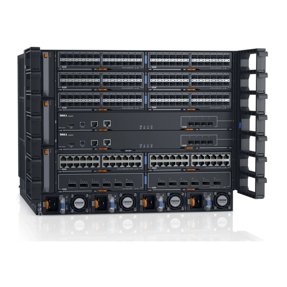
Dell Networking C9010 Getting Started Guide software configuration instructions Software configuration Dell Networking Configuration Guide for the C9000 Series Command-line interface Dell Networking Command-Line Reference Guide for the C9000 Series Latest updates Dell Networking C9010 and C1048P Release Notes About This Guide... - Page 4 C9010 Hardware Description The C9010 switch is part of Dell Networking's next-generation LAN solution, providing a scalable switch that offers a path to higher density 10GbE and 40GbE capability. You can deploy the C9010 switch as an access or aggregation/core switch for installations in which a modular switch is preferred. For larger port requirements, you can also connect C1048P port extenders (PEs) as access devices.
-
Page 5: Unpacking The Switch
The switch and its accessories ship in a single container. Before unpacking the switch, inspect the container and immediately report any evidence of damage. Verify that you have received your ordered items. If any item is missing or damaged, contact your Dell Networking representative or reseller for assistance. - Page 6 • QSFP+ DAC cables • DB-9 adapter • Dell ReadyRails™ kit (#1 and #2 Phillips and flat-tipped screwdrivers required) with four cage nuts • Rack mount tray • C1048P port extenders for use with the C9010 Before You Start: Site Preparation Before installing the C9010 switch, make sure that your installation site meets these requirements: •...
- Page 7 airflow, and ventilation. Make sure that the AC power cord can reach the power connector on the front panel of a power supply unit from the power outlet. • Airflow: On the C9010, airflow is from the right to the left side as you face the switch. Hot air is expelled from the left side.
-
Page 8: Installing The Hardware
After you install the switch in a rack and power it up, perform the initial software configuration and connect the switch to a network as described in the Dell Networking C9010 Getting Started Guide. Installing the Chassis in a Two-Post Threaded-Hole Rack You can install the chassis in a 2-post threaded-hole rack by following the tooled procedure in this section. - Page 9 NOTE: The installation procedure in this section describes how to install the C9010 in a 2-post rack using the rack bar provided in the base configuration package. For information about how to use Dell ReadyRails or a rack mount tray to install the C9010, follow the instructions in Installing Dell ReadyRails Installing a Rack Mount Tray.
- Page 10 Using a flat-head screwdriver, remove the bracket screws (item 1 in Figure 3) and unscrew the thumb screws to remove the bracket (item 2 in Figure 3) attached to each chassis flange. Figure 3. Removing Brackets from the Chassis Installing the Hardware...
- Page 11 Use an equipment lift or two people to lift the empty chassis without blanks (item 1 in Figure 4) and align the rack-mount screw holes on each flange of the chassis with the holes in the equipment rack. Rest the chassis on top of the rack bar (or rack tray, if installed). Slide the chassis so that the holes in the side flanges align with the holes in the rack posts.
-
Page 12: Installing The Chassis In A Four-Post Rack
Verify that the chassis is securely installed in the two rack posts and does not sag. To prevent sagging, support the back of the chassis by using a rack mount shelf or Dell ReadyRails as described in Step 3. Figure 5. Chassis Installed in a 2-Post Rack NOTE: To allow for increased airflow, you can remove the rack bar from the front posts. - Page 13 WARNING: To prevent bodily injury when mounting or servicing this unit in a rack, take special precautions to ensure that the system remains stable. The following guidelines are provided to ensure your safety: • If your chassis is the only unit in the rack, mount it at the bottom of the rack. •...
- Page 14 NOTE: The installation procedure in this section describes how to install the C9010 in a 4-post rack using the rack bar provided in the base configuration package. For information about how to use Dell ReadyRails or a rack mount tray to install the C9010, follow the instructions in Installing Dell ReadyRails Installing a Rack Mount Tray.
- Page 15 To install the chassis, first insert four cage nuts into the front rack posts at the same height as the thumb screws on each chassis flange. On each post, install the lower cage nut in the top post hole 3 RUs above the rack bar; install the upper cage nut in the bottom post hole 5 RUs above the lower cage nut (8 RUs above the rack bar).
- Page 16 Use two people or an equipment lift to align the chassis rack-mount holes with the cage nuts in the front posts (items 1 and 2 in Figure 8). Rest the chassis on top of the rack bar (or rack tray or ReadyRails, if installed).
- Page 17 Using Dell ReadyRails (Optional) Dell Networking offers the Dell ReadyRails rack mounting system as an option to ease the installation of a switch in a 2-post or 4-post rack. You must order a ReadyRails kit as a separate item; it is not part of the C9010 base configuration.
- Page 18 • Two spacers that allow you to secure the chassis flanges flush on the front rack posts (items 9 and 10 in Figure 10) Figure 10. Dell ReadyRails for 2- and 4-Post Racks Left chassis rail Right chassis rail Left ReadyRail bracket for 2-post racks...
- Page 19 Tool-less Method for a Non-Threaded-Hole Rack Attaching ReadyRails to the Rack Remove the front and rear parts of the left 4-post rail from the Dell ReadyRails kit and slide the parts together. (The front and rear parts of a rail may arrive pre-assembled.) Install a cage nut (item 2 in Figure 11) in the left front post at the desired height of the thumb screw on the left front rail.
- Page 20 Figure 11. Installing Tool-less Rails in a Non-Threaded-Hole Rack Installing the Hardware...
- Page 21 Attaching the Chassis Rails • Remove the two chassis rails from the Dell ReadyRails kit. • Align the holes on the right and left chassis rails with the mounting studs at the bottom of each side of the chassis (orange arrows and item 1 in Figure 12).
- Page 22 Attaching the Spacers Place each spacer (item 2 in Figure 13) over the four pins at the back of each chassis flange. Then slide each spacer down so that it locks into place and is flush with the flange. Figure 13. Attaching Spacers on the Chassis Flanges Installing the Hardware...
- Page 23 Installing ReadyRails: Tooled Method for a Threaded-Hole Rack To install ReadyRails using a tooled method in a threaded-hole 2- or 4-post rack: Locate the front rack rails in the Dell ReadyRails kit (items 5 and 6 in Figure 10). •...
- Page 24 Using a flat-tipped screwdriver, remove the bracket subassembly and four pins (items 1 and 2 in Figure 15) from the front and rear of each rail. Pull on each subassembly to fully remove it. Figure 15. Installing Tooled Rails in a Threaded-Hole Rack Attach the front of each rail to the front rack posts using the screws provided with the rack.
- Page 25 You can also use a rack mount tray to install the C9010 switch in a 2- or 4-post rack. Purchase the tray as a separate item. NOTE: If the use of a rack bar or Dell ReadyRails does not satisfy your C9010 installation requirements, Dell Networking recommends using a rack mount tray to support the weight of a C9010 switch in a 2- or 4-post rack.
- Page 26 To install a rack mount tray in a rack, follow the instructions provided with the tray kit. Decide where you want to mount the switch in the rack. Position the tray at that height and tighten it to the rack posts using the screws shipped with the tray (items 1 to 4 in Figure 17).
-
Page 27: Installing A Fan Module
Attach a grounding cable to the chassis lug by inserting a 6-gauge cable (item 1 in Figure 18). Using a hand-crimping tool (Tyco Electronics 58433-3 or equivalent), crimp the lug (item 2 in Figure 18) so that the cable is held securely. Figure 18. -
Page 28: Installing Rpms And Line Cards
Slide the first fan module into fan slot 0 by pushing the handle (item 1 in Figure 19) forward into the uppermost fan slot (item 2 in Figure 19). Gently push the front of the module until it clicks into place. The fan module should be flush with the chassis. - Page 29 Before you install an RPM in the C9010 chassis, review these guidelines: • Although the C9010 switch can operate with one RPM, Dell Networking recommends two RPMs for redundancy and to provide more bandwidth to each line card. One RPM provides 120 Gigabits of bandwidth to each line card;...
- Page 30 Open the left and right ejector levers (item 1 in Figure 21) on an RPM by pressing in the orange tab (item 2 in Figure 21) and rotating it to the right so that both levers snap into the open position. Figure 21.
- Page 31 The arrow in slot 10 (item 2 in Figure 22; labelled R0 on the chassis) identifies the slot in which you insert the first RPM. Align the card with the guide and gently slide it into the slot by holding the two ejector levers in the fully open position and pushing the card forward.
- Page 32 • To control airflow for adequate system cooling, personal safety, and EMI containment during operation, install a blank in any empty line card slot. Install an operational line card module or a blank in each line card slot. Always replace a line card or blank panel immediately. •...
-
Page 33: Installing A Power Supply
AC power supply with an IEC 60320 C19 power cable. The power supply is rated as 1450W at 100~120 VAC and 2900W at 200~240 VAC. NOTE: If a power supply fails, Dell Networking recommends that you replace it as soon as possible. C9010 power supply units are hot-swappable. -
Page 34: Installing The Cable Management System
Figure 24. Installing the First Power Supply Installing the Cable Management System To organize network cables and minimize the obstruction from cables when you insert, remove, and view chassis components, you can install a cable management system on the front of the chassis. Using the cable management system, you can attach the maximum number of cables in C9010 line card ports. - Page 35 C9010 base configuration. The two brackets are identical. Install them on the right and left chassis flanges. Figure 25. Cable Management System NOTE: Dell Networking recommends that you install the cable management system after you install the chassis in a rack and all of the chassis components in the chassis. Installing the Hardware...
- Page 36 To install the cable management system, mount both brackets on the right and left sides of the chassis: Align the openings on the inside of a bracket with the pins (item 1 in Figure 26) and thumb screws on each chassis flange. Figure 26.
- Page 37 C9010, but Dell Networking does not guarantee their performance. If you plug a non-Dell qualified optic into a PE port, the Dell Networking OS detects it and makes it operational. The system displays a syslog message similar to the following:...
-
Page 38: Powering Up The System
NOTE: Non-Dell qualified 40G transceivers are not supported on the C9010. If you insert a non-Dell qualified 40G transceiver into a C9010 40GbE port, the switch places the interface in an error- disabled (operationally down) state and generates a syslog message, such as: %C9000LC0640:8 %IFAGT-2-TRANSCEIVER_UNSUPPORTED_ERROR: Transceiver in slot 8 port 4 unrecognized, putting interface in operational-down state. -
Page 39: Checking Led Status
RPMs, line cards, power supplies, and fan modules. NOTE: You can also check system status using CLI show commands and the Simple Network Management Protocol (SNMP). For more information about these options, see the Dell Networking Command Line Reference and Configuration Guides for the C9000 Series. - Page 40 Color / Description • Flashing amber — Error condition or reload is in progress. • Solid green — Normal operation Fan status LED • Flashing amber — Error condition in a fan module • Solid green — Normal operation Power supply status •...
- Page 41 Color / Description • Solid amber — 40G link is up but operating at lower speed (less than 40G). • Flashing amber — 40GbE port is transmitting/receiving data at a lower speed (less than 40G). • Flashing amber (1 second on, 1 second off) — Port beacon used to locate port •...
- Page 42 Table 4. 1/10GbE SFP+ and 1/10GbE RJ-45 Port LEDs Color / Description • Off — No link 1/10GbE Port Link/ Activity LED • Solid green — 10G link is up and 10GbE interface is enabled. • Flashing green — 10GbE port is transmitting/receiving data. •...
- Page 43 Figure 32. PSU LEDs PSU LED: DC output (on handle) PSU LED: AC input power Table 6. PSU LEDs Color / Description • Solid green — Normal DC power output PSU: DC output • Solid amber — Alarm: PSU is not operational due to a fault condition. •...
- Page 44 Removing the Chassis from a Rack To remove the chassis from a 2-post or 4-post equipment rack, follow the instructions in this section. WARNING: Due to the weight of a fully populated C9010 chassis, never pull a full chassis out of a rack with ReadyRails.
- Page 45 Figure 33. Removing the Chassis from a Rack Removing the Chassis from a Rack...
- Page 46 Dell Networking Support The Dell Networking Support site provides a range of documents and tools to assist you with effectively using Dell Networking equipment and mitigating the impact of network outages. Through the support site you can obtain technical information regarding Dell Networking products, access software upgrades and patches, download available management software, and manage your open cases.
- Page 47 Figure 34. C9010 Service Tag Dell Networking Support...
-
Page 48: Technical Specifications
Technical Specifications The following tables describe the technical specifications for the C9010 switch. Table 7. Chassis Physical Design Parameter Specifications Height 13.9 inches (35.26 cm) Width 17.4 inches (44.20 cm) Depth 18.0 inches (45.70 cm) 55 lbs (24.95 kg) empty Chassis weight 152 to 165 lbs (68 to 74.84 kg) fully loaded, depending on the type of line cards installed... -
Page 49: Agency Compliance
This product is in conformity with the protection requirements of EU Council Directive 2004/108/EC on the approximation of the laws of the Member States relating to electromagnetic compatibility. Dell Networking can not accept responsibility for any failure to satisfy the protection requirements resulting from a non-recommended modification of this product, including the fitting of non-Dell Networking option cards. -
Page 50: Japan: Vcci Compliance For Class A Equipment
Information Technology Equipment (VCCI). If this equipment is used in a domestic environment, radio disturbance may arise. When such trouble occurs, the user may be required to take corrective actions. WARNING: Use the AC power cords with Dell Networking equipment only. Do not use Dell Force10 AC power cords with any unauthorized hardware. -
Page 51: Safety Standards And Compliance Agency Certifications
Figure 38. Korean Package Label Safety Standards and Compliance Agency Certifications • CUS UL 60950-1, 2nd Edition or later • CSA 60950-1-03, 2nd Edition or later • EN 60950-1, 2nd Edition or later • EN 60825-1, 1st Edition or later •... -
Page 52: Product Recycling And Disposal
Networking encourages owners of information technology (IT) equipment to responsibly recycle their equipment when it is no longer needed. Dell Networking offers a variety of product return programs and services in several countries to assist equipment owners in recycling their IT products.