Pioneer DDJ-T1 Service Manual
Hide thumbs
Also See for DDJ-T1:
- Operating instructions manual (96 pages) ,
- Operating instruction (92 pages) ,
- Service manual (20 pages)
Table of Contents
Quick Links
DJ CONTROLLER
DDJ-T1
THIS MANUAL IS APPLICABLE TO THE FOLLOWING MODEL(S) AND TYPE(S).
Model
Type
DDJ-T1
SVYXJ8
DDJ-T1
UXJCB
DDJ-T1
FLPXJ
DDJ-T1
KXJ5
DDJ-T1
AXJ5
For details, refer to "Important Check Points for good servicing".
PIONEER CORPORATION
PIONEER ELECTRONICS (USA) INC. P.O. Box 1760, Long Beach, CA 90801-1760, U.S.A.
PIONEER EUROPE NV Haven 1087, Keetberglaan 1, 9120 Melsele, Belgium
PIONEER ELECTRONICS ASIACENTRE PTE. LTD. 253 Alexandra Road, #04-01, Singapore 159936
PIONEER CORPORATION
Power Requirement
AC 100 V to 240 V
AC 100 V to 240 V
AC 100 V to 240 V
AC 100 V to 240 V
AC 100 V to 240 V
1-1, Shin-ogura, Saiwai-ku, Kawasaki-shi, Kanagawa 212-0031, Japan
2011
DDJ-T1
K-IZV FEB.
ORDER NO.
RRV4164
Remarks
2011 Printed in Japan
Table of Contents

Related Manuals for Pioneer DDJ-T1


Summary of Contents for Pioneer DDJ-T1
- Page 1 PIONEER CORPORATION 1-1, Shin-ogura, Saiwai-ku, Kawasaki-shi, Kanagawa 212-0031, Japan PIONEER ELECTRONICS (USA) INC. P.O. Box 1760, Long Beach, CA 90801-1760, U.S.A. PIONEER EUROPE NV Haven 1087, Keetberglaan 1, 9120 Melsele, Belgium PIONEER ELECTRONICS ASIACENTRE PTE. LTD. 253 Alexandra Road, #04-01, Singapore 159936...
-
Page 2: Safety Information
PIONEER Service Manual. A subscription to, or additional copies of, Also test with plug reversed Earth PIONEER Service Manual may be obtained at a nominal (Using AC adapter ground charge from PIONEER. plug as required) - Page 3 To protect products from damages or failures during transit, the shipping mode should be set or the shipping screws should be installed before shipment. Please be sure to follow this method especially if it is specified in this manual. DDJ-T1...
-
Page 4: Table Of Contents
11.5 TCHB, JOGB and LEDB ASSYS ..........................108 11.6 CDJ1B ASSY ................................112 11.7 CDJ2B ASSY ................................116 11.8 DJMB ASSY................................120 11.9 CHFD and CRFD ASSYS ............................124 11.10 MICB ASSY................................128 11.11 HPJK ASSY ................................129 11.12 USBB ASSY................................130 12. PCB PARTS LIST ................................131 DDJ-T1... -
Page 5: Service Precautions
After the EEPROM is replaced, be sure to copy the program for the USB controller to it. For details, see “8.4 Copying the Program for the USB Controller.” Replacement of the MAIN_UCOM When replacement of the MAIN_UCOM (IC701) is required, order a microcomputer dedicated for service (PEG850A8-K). DDJ-T1... -
Page 6: Specifications
S/ N ratio (when playing on computer) without notice. MASTER OUT 1..103 dB or greater (at rated output) MASTER OUT 2..103 dB or greater (at rated output) Accessories • TRAKTOR Pioneer DDJ-T1 EDITION software CD-ROM • AC adapter (DXX2665) (DWR1491) • Driver software CD-ROM (DXX2666) •... -
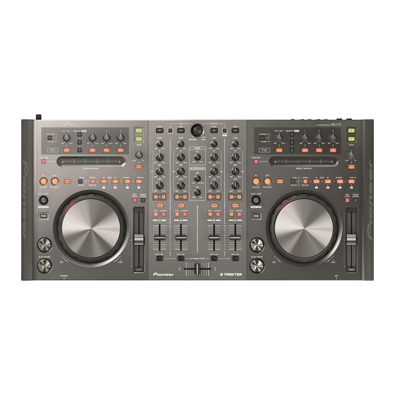
Page 7: Panel Facilities
2.2 PANEL FACILITIES Rear panel Front panel DDJ-T1... -
Page 8: Control Panel
Control panel DDJ-T1... - Page 9 1 Browser DDJ-T1...
- Page 10 2 Deck DDJ-T1...
- Page 11 3 Mixer DDJ-T1...
- Page 12 4 Effect DDJ-T1...
-
Page 13: Basic Items For Service
Purpose of use / Remarks USB cable GGP1188 for PC connection, accessory AC adapter DWR1491 Accessory (Note: The power plug part is different.) Lubricants and Glues List Name Part No. Remarks Lubricating oil GYA1001 Refer to “9.5 JOG SECTION”. DDJ-T1... -
Page 14: Pcb Locations
2..CDJ1B ASSY DWS1430 1..DJM2 ASSY DWM2426 2..JOGB ASSY DWS1432 2..DJMB ASSY DWX3211 2..TCHB ASSY DWS1433 2..JACB ASSY DWX3214 2..LEDB ASSY DWS1434 2..USBB ASSY DWX3222 1..CDJ2 ASSY DWM2423 2..CDJ2B ASSY DWS1431 2..JOGB ASSY DWS1432 2..TCHB ASSY DWS1433 2..LEDB ASSY DWS1434 DDJ-T1... - Page 15 DDJ-T1...
-
Page 16: Block Diagram
DJMB ASSY HP_L DDD1547- 1mm pitch / GND_AH L=100mm/TAPE LENGTH=8mm,1 MUTE (DWX3211) K M 2 0 0 N A 9 C N 4 8 0 1 JA4801 HPJK ASSY HP OUT DKN1622- OP AMP (DWX3216) JA4802 HP OUT (mini) CKS4124- DDJ-T1... - Page 17 K M 2 0 0 N A 3 L MIC IN MICB ASSY JA4601 OP AMP DKN1614- K M 2 0 0 N A 3 L PF03PP-C06 2mm pitch C N 4 3 0 1 (DWX3215) L=60mm GND_AD CRFD ASSY AD_CROSSF V+3R3_AD (DWX3213) DDJ-T1...
-
Page 18: Overall Block Diagram
Key In [12:9][4:1] Grid[7:4] IC1101 Key Buffer Key In[8:5] Key In[13][8:5] IC1102 Key Buffer CN6002 JH6001 LED[11:6] CN3201 CN3301 IC301 IC303 AUX/MIC CN3503 IC302 CDJ2B ASSY TCHB ASSY JOGB ASSY CN4001 CN4601 VR4601 JA4601 MIC IN IC4601 AUX/MIC SW MICB ASSY DDJ-T1... - Page 19 CN6002 JOG1_1/1_2 CN3301 CN3201 IC106 CN3003 Reset IC IC303 AUX/MIC Fault_Det Circuit CDJ1B ASSY Trim Fader TCHB ASSY JOGB ASSY CN4301 CN4001 CN4002 MATRIX Circuit CHFD ASSY FD SATRT SW MATRIX Circuit CN4202 CN2001 CRFD CRFD ASSY DJMB ASSY DDJ-T1...
-
Page 20: Power Block Diagram
5V→3.3V S-1200B33 V+5_D V+5_A IC101 IC103 D/D_CONV 5V_REG 5V→6V 6V→5V BD9851EFV S-1200B50 AUDIO AMP(MASTER) RNB4580F V+5_D IC101 IC501 D/D_CONV 5V→-6V BD9851EFV AUDIO AMP(HP) NJM4565MD IC305 SW AMP(AUX/MIC) NJM2121MD x2 IC301, IC302 OPAMP x1 OPAMP x4 JACB ASSY MICB ASSY DDJ-T1... - Page 21 CDCB 2 Assy are interchangeably used and handled similarly in their production management. M2121MD x2 DJMB ASSY 301, IC302 V+5_D V+5_D V+3R3_AD V+3R3_AD V+3R3_AD MIXER V+3R3_AD V+3R3_AD V+3R3_AD CH FADER CROSS OPAMP x1 FADER HPJK ASSY CRFD ASSY CHFD ASSY DDJ-T1...
-
Page 22: B 5. Diagnosis
Display initial setting Headphones level setting To normal main loop processing • Power monitoring/switching • MIC/AUX switching • Detection of change in operating elements • USB transmission (transmission of operating element data) • USB reception (reception and indication of display data) DDJ-T1... -
Page 23: Troubleshooting
UCOM Assy The regulator (IC102), the USB_UCOM (IC202), SUPPLY BLOCK USB_UCOM on If V+3R3_USB is abnormal (2.7 V or less) USB_UCOM or their peripheral circuits may be defective. DIAGRAM the UCOM Assy and the V+5_USB is normal (4.5 V–5.25 V) DDJ-T1... - Page 24 (For example, although some of the LEDs UCOM Assy startup error Error Indications If the normal status is not recovered after all above steps light properly, the unit is not started up are performed, the MAIN_UCOM (IC701) may be properly.) defective. DDJ-T1...
- Page 25 SW may be defective. switches and main microcomputer (IC701). Basic Operation If the symptom persists after the above Go to [7-1] Basic Operation Check of the Defective MAIN_ UCOM Assy Check of the corrections. Microcomputer. UCOM (IC701) MAIN_UCOM DDJ-T1...
- Page 26 If the Needlepad operates improperly although there is no UCOM/CDCB Check that no foreign matter is between commands from foreign matter between the Needlepad board and the Assy the Needlepad board and the cabinet. the needlepad are cabinet, check [2] above. recognized. DDJ-T1...
- Page 27 Adjust Plate is reached, Rotation Load Adjustment.” gear, or cam plate Rotation Load shavings from the worn-out washer may have Adjustment. increased the friction. Replace the washer, load gear, and cam plate with new ones, then reassemble. DDJ-T1...
- Page 28 OP amp (IC4404), check the soldering interrupted on the line from CN4401 to the JACB Assy 10.1 JACB ASSY /defective parts status of the OP amp. If it is properly soldered, then jacks (JA4403). the OP amp itself may be defective. DDJ-T1...
- Page 29 If it is not, check Q301. If the symptom persists, Loose connection ASSY (2/6) UCOM Assy • When AUX is selected: “H” soldering of the MAIN_UCOM (IC701) or the MAIN_ /defective parts 10.17 WAVEFORMS • When MIC is selected: “L” UCOM itself is defective. MIC,AUX No. ) DDJ-T1...
- Page 30 If the key input circuit of the board connected is Check the connection of the FFC cable. 10.7 UCOM Assy normal, the KEY Buffer ICs (IC1101 and 1102) may Check also the key input circuit of the PCB corresponding ASSY (6/6) be defective. Assy connected. to each key DDJ-T1...
-
Page 31: Voltage Monitoring
5 If the voltage of any power IC is abnormal, the circuit that uses that power or the power IC itself may be defective. 6 Repair the defective part then check that the voltage of the repaired part becomes normal. 7 Return R147 to its original position on the UCOM Assy. Note: This step will enable power monitoring. DDJ-T1... -
Page 32: How To Check Operations Using The Traktor Software
(latency time) over the standard Windows audio driver. In addition, when this driver is installed, the DDJ-1 Version Display Utility is installed, as well. With this utility installed, you can confirm the versions of the driver software and DDJ-T1 firmware. - Page 33 Double-click on the “Traktor” icon on the desktop. Select “Pioneer” on the pulldown menu for the Click on “Run Demo.” manufacturer and “DDJ-T1” for the model then click on “Next.” Select “No Timecode Control” then click on “Next.” Click on “Next.”...
- Page 34 TRAKTOR. You can restart and use the demo version as many times as you wish. • On the normal version of TRAKTOR PIONEER DDJ-T1 EDITION, the external inputs (AUX/MIC) are assigned to Deck D, but on the demo version they are assigned to Deck A.
-
Page 35: Connection Examples
4. On the TRAKTOR screen and via the audio output, check if the connected audio signal is input. Note: With the initial setting of TRAKTOR Pioneer DDJ-T1 EDITION, the audio signal from an external device connected via the AUX IN or MIC connector is input to Deck D. -
Page 36: Service Mode
It is the mode which judges the quality of the load when rotating JOG dial. 3 Error display. Error detection and its display method of a device are shown. 4 Firmware update. Explanation of the method of firmware update. Refer to the "8.3 UPDATING OF THE FIRMWARE." DDJ-T1... -
Page 37: Details On Service Mode
JOG LED ALL ON MIXER LOAD A BUTTON FX 1 A LOAD B BUTTON FX 1 B LOAD C BUTTON FX 1 C LOAD D BUTTON FX 1 D TREE BUTTON HEADPHONE CUE A FAVORITES/REC BUTTON HEADPHONE CUE B DDJ-T1... - Page 38 FX 2 C CH FADER START D SLIDE SWITCH FX 2 D CROSS FADER SLIDE VOLUME Note: It cannot check only by the controller. Please connect with TRAKTOR, use it and check a related display in the usual mode. DDJ-T1...
- Page 39 LOOP ACTIVE lighting NG (Light) LOOP OUT lighting NG (Heavy) LOOP IN lighting Measurement is performed although the number of times is not displayed 5th henceforth. Each time, an average is taken and a result is displayed on LED. DDJ-T1...
-
Page 40: About The Device
Part No. Ref No. Assy Main microcomputer, DYW1801 MAIN UCOM IC701 UCOM Assy All operating elements/LED control PEG850A8-K USB UCOM USB control, audio control TUSB3200A IC202 UCOM Assy IC2001 CDCB 1 Assy Needle search control AD7147ACPZ500RL7 IC2101 CDCB 2 Assy DDJ-T1... -
Page 41: Disassembly
Rotary Knob L (Black) Slider Knob 1 Slider Knob 2 Slider Knob Stopper (DAA1262) ×7 (DAA1261) ×12 (DAC2684) ×5 (DAC2685) ×5 (DNK5888) ×5 White Slider Knob 2 White White Black Black Slider Knob 1 Black Gray Slider Knob Stopper DDJ-T1... - Page 42 Slider knob 2 *: During reassembly, fully push down Slider knob 2 until it is Tweezers Protective material dented into Slider knob 1. 4 Remove the slider knob 1. 5 Remove the slider knob stopper. Slider knob 1 Slider knob stopper DDJ-T1...
- Page 43 ×2 Foot • Bottom view (4) Remove the six screws. (BPZ30P080FNI) (5) Remove the 14 screws. (BBZ30P060FTC) ×3 (6) Remove the chassis A. Chassis A ×14 Screw tightening order ×3 The other screws are random order. • Bottom view DDJ-T1...
- Page 44 (1) Remove the two screws. (BPZ30P080FNI) (2) Remove the FFC guard M. (3) Remove the 20 screws. (BPZ30P080FNI) ×2 (4) Remove the three cord clampers. (5) Remove the mixer and fader section. ×20 FFC guard M Mixer and fader section • Bottom view DDJ-T1...
- Page 45 (4) Remove the two screws. (IMZ30P040FTC) ×8 Cap/FDR (5) Remove the VR stay L. ×2 VR stay L DJMB Assy CRFD Assy CHFD Assy Clamper styling JACB Assy CDCB 2 Assy CN501 CN4403 CN301 CN901 CN2101 Clamper UCOM Assy CN302 DDJ-T1...
- Page 46 (12) Remove the phone spacer. (13) Remove the one screw. (BBZ30P060FTB) Raer (14) Remove the two screws. (BPZ30P080FTB) (15) Remove the two screws. (BPZ30P080FNI) ×2 (16) Remove the JACB Assy. • Bottom view Screw tightening order MICB Assy HPJK Assy DDJ-T1...
- Page 47 (1) Remove the five nuts and five washers. (2) Remove the two VR stays S. ×4 Rear stay R Rear stay L (3) Remove the rear stay L and R. ×4 VR stay S VR stay S CDJ2B Assy CDJ1B Assy DDJ-T1...
- Page 48 The other screws are random order. LEDB Assy • Bottom view [3-4] LEDB Assy (1) Disconnect the one connector. (CN6002) LEDB Assy (2) Disconnect the one connector. (CN3301) (3) Remove the LEDB Assy. CN6002 JOGB Assy TCHB Assy CN3301 DDJ-T1...
-
Page 49: Each Setting And Adjustment
How to Confirm the Version of the DDJ-T1 Firmware on Mac OS X 1. Select “Application” then “Utility,” then start “System Profiler.” 2. Click on “USB” then “DDJ-T1.” The version of the DDJ-T1 firmware is displayed in the version field. DDJ-T1... -
Page 50: Updating Of The Firmware
When update goes wrong, USB cable is extracted on the way or the power supply has been turned off, usual DJ operation becomes impossible after that. In this case, the recovery mode which only updates operates (State of 2 or 3 in "[3] Error display"). Update program can be used like usual also at this time. DDJ-T1... -
Page 51: Copying The Program For The Usb Controller
Copy the program for the USB controller according to the following procedure after the EEPROM (IC201) on the UCOM Assy is replaced: 1 Turn the DDJ-T1 off then connect this unit with a PC, via USB. 2 Set the POWER switch to ON while simultaneously holding the FUNCTION and LOOP OUT buttons on the left deck pressed. -
Page 52: Jog Dial Rotation Load Adjustment
Because the load value is too large, detach and shift the Adjust Plate toward the – direction then secure it. After adjustment of the Adjust Plate location, repeat Steps 1 to 3 until the measurement result becomes OK. Adjust plate Fig. 1 DDJ-T1... - Page 53 DDJ-T1...
-
Page 54: Exploded Views And Parts List
For the applying amount of lubricants or glue, follow the instructions in this manual. (In the case of no amount instructions, apply as you think it appropriate.) 9.1 PACKING SECTION UXJCB only SVYXJ8 only UXJCB KXJ5 AXJ5 SVYXJ8 only only only only FLPXJ only KXJ5 only Front DDJ-T1... - Page 55 30 Pad A DHA1871 31 Pad B DHA1872 32 Packing Case See Contrast table (2) (2) CONTRAST TABLE DDJ-T1/SVYXJ8, UXJCB, FLPXJ, KXJ5 and AXJ5 are constructed the same except for the following: Mark Symbol and Description DDJ-T1/SVYXJ8 DDJ-T1/UXJCB DDJ-T1/FLPXJ DDJ-T1/KXJ5 DDJ-T1/AXJ5...
-
Page 56: Exterior Secion
9.2 EXTERIOR SECION Refer to "9.3 PCB LAYER SECTION" . DDJ-T1... - Page 57 17 • • • • • 18 Screw PMB30P080FTB 19 Screw BBZ30P060FTC 20 Screw BPZ30P080FNI (2) CONTRAST TABLE DDJ-T1/SVYXJ8, UXJCB, FLPXJ, KXJ5 and AXJ5 are constructed the same except for the following: Mark Symbol and Description DDJ-T1/SVYXJ8 DDJ-T1/UXJCB DDJ-T1/FLPXJ DDJ-T1/KXJ5 DDJ-T1/AXJ5 Chassis...
- Page 58 "9.4 BUTTON LAYER SECTION" . "9.5 JOG SECTION" . Either the CDCB 1 Assy or CDCB 2 Assy is assembled here. The CDCB 1 Assy and CDCB 2 Assy are interchangeably used and handled similarly in their production management. DDJ-T1...
- Page 59 DNH2961 37 Rear Stay R DNH2962 38 VR Stay L DNH2963 39 VR Stay S DNH2964 40 CDC Stopper DNK5863 41 Cord Hook DNK5928 42 Cord Clamper (Steel) RNH-184 43 Binder ZCA-SKB90BK 44 Nut M12 DBN1018 45 Nut NKX2FTC DDJ-T1...
- Page 60 9.4 BUTTON LAYER SECION • Bottom view DDJ-T1...
- Page 61 *: Note that there are two types of button S, as some of them have to be split into two when used. (2) CONTRAST TABLE DDJ-T1/SVYXJ8, UXJCB, FLPXJ, KXJ5 and AXJ5 are constructed the same except for the following: Mark Symbol and Description...
-
Page 62: Jog Section
9.5 JOG SECTION STPB ASSY Lubricating oil (GYA1001) LEDB CN6002 LEDB JH6001 Encoder arm Hook Arm spring Hook Lubricating oil (GYA1001) Bottom view DDJ-T1... - Page 63 DNK5945 21 Roller B Assy DXB1877 22 JOG Holder Assy DXB2002 23 Binder ZCA-SKB90BK 24 Washer WA41D070D025 25 Washer WT32D080D050 26 • • • • • 27 • • • • • 28 Screw BPZ20P060FTC 29 Screw (FE) DBA1265 DDJ-T1...
-
Page 64: Schematic Diagram
NOTES is No Mount RS1/10SR***J I C 4 4 *CAPACITORS C 4 4 3 5 Indicated in Capacity/Voltage(V) RS1/10SR****D unless otherwise noted. u F , p CKSRYB***K *RESISTORS CCSRCH***J Indicated in 5% tolerance unless otherwise noted. k CEJQ*** V-6M DDJ-T1... - Page 65 R 4 4 3 6 R 4 4 5 2 I N C 2 0 0 2 A C 1 1 0 0 u / 1 6 C 4 4 3 1 GND_AM GND_AM GND_FM2 GND_PM V-6M GND_AM MASTER OUT AUX IN circuit DDJ-T1...
-
Page 66: Ucom Assy (1/6)
V O U T V S S V S S R 1 3 3 R 1 3 4 O N / O F F O N / O F F 1 0 k 1 0 k S-1200B50-M5 S-1200B33-M5 GND_D GND_D DDJ-T1... - Page 67 USB_SREQ USB_RST USB_BUS 4:1D;4:5B NOTES is No Mount RS1/10SR***J GND_D RS1/16SS***J RS1/8SQ***J RS1/10SR****D, or RS1/16SS****D CKSRYB***K *CAPACITORS Indicated in Capacity/Voltage(V) CCSRCH***J unless otherwise noted. u F , p CKSSYB***K *RESISTORS Indicated in 5% tolerance CCSSCH***J unless otherwise noted. k DDJ-T1...
-
Page 68: Ucom Assy (2/6)
NOTES Indicated in Capacity/Voltage(V) unless otherwise noted. u F , p H S U 1 1 9 is No Mount *RESISTORS RS1/10SR***J Indicated in 5% tolerance unless otherwise noted. k RS1/16SS***J RS1/8SQ***J RS1/10SR****D, or RS1/16SS****D CKSRYB***K CCSRCH***J CKSSYB***K CCSSCH***J DDJ-T1... - Page 69 R 3 3 9 R 3 1 3 R 3 1 6 4 . 7 k 8 . 2 k 6 . 8 k C 3 2 4 C 3 3 7 4 7 u / 1 6 GND_P GND_AH DDJ-T1...
-
Page 70: Ucom Assy (3/6)
C C L K A O U T R 1 0 0 u / 1 6 4 . 7 k 3 . 3 k DAC_CDTI C D T I AK4387ET R 5 2 2 MASTER DAC 2/6,4/6 GND_AM GND_D GND_AM AUDIO_CONT 2:1D;2:3A;2:8D;2B;4:9H DDJ-T1... - Page 71 I C 5 0 1 NJM4580MD R 5 0 4 R 5 0 6 3 . 3 k GND_AM C 5 0 8 GND_P C 5 1 0 C C H 1 5 6 5 - A 100u 16V GND_P GND_AM GND_AM DDJ-T1...
-
Page 72: Ucom Assy (4/6)
G1 A B C Y0 Y1 Y2 Y3 Y4 Y5 Y6 Y7 GRID5 LED_SEG GRID4 12D;2G;8A;5:11H;5:4H;6:4B X X X GRID3 X G 2 B GRID2 X G 2 A GRID1 GRID0 R 7 1 9 V C C R 7 5 2 IC702 GND_D DDJ-T1... - Page 73 P 1 _ 0 / C T S 6 / R T S 6 / D 8 2 2 0 GND_AD GND_D NOTES is No Mount RS1/10SR***J RS1/16SS***J RS1/8SQ***J RS1/10SR****D, or RS1/16SS****D AUDIO_CONT 2:1D;2:3A;2:8D;3:2B;3:2G CKSRYB***K 2/6,3/6 CCSRCH***J CKSSYB***K CCSSCH***J 3G;6A;5:4A;5:8A DDJ-T1...
-
Page 74: Ucom Assy (5/6)
R 9 4 2 LED_7 GND_D TP943 LED_8 R 9 4 3 LED_8 TP944 R 9 4 4 LED_9 LED_9 TP945 R 9 4 5 LED_10 LED_10 TP946 LED_11 R 9 4 6 4/6,6/6 LED_11 4:12D;4:2G;4:5H;4:8A;11H;6:4B TP935 LED_SEG GND_D DDJ-T1... - Page 75 R 9 8 1 LED_1 GND_D TP980 R 9 8 2 LED_2 LED_2 TP981 LED_3 R 9 8 3 LED_3 TP982 R 9 8 4 LED_4 LED_4 TP983 LED_5 R 9 8 5 LED_5 4/6,6/6 TP972 4:12D;4:2G;4:5H;4:8A;4H;6:4B LED_SEG GND_D DDJ-T1...
-
Page 76: Ucom Assy (6/6)
C 1 1 0 6 KEY_IN12 KEY4 C 1 1 0 7 KEY_IN11 KEY12 C 1 1 0 8 KEY_IN10 KEY11 C 1 1 0 9 KEY10 G N D R 1 1 1 0 1 0 0 TC74LCX541FK 4:3G;4:5G;8H GND_D DDJ-T1... - Page 77 C 1 1 1 2 KEY_IN6 KEY7 C 1 1 1 3 KEY_IN5 KEY6 C 1 1 1 4 KEY_IN13 KEY5 C 1 1 1 6 KEY13 R 1 1 0 5 4:3G;4:5G;4H 1 0 0 G N D TC74LCX541FK GND_D DDJ-T1...
-
Page 78: Cdcb 1, Cdcb 2, Tchb And Jogb Assys
R2115 A D 7 1 4 7 A C P Z 5 0 0 R L 7 CDC_DSO V+3R3_CDC C 2 1 0 1 0 . 0 1 u / 5 0 GND_CDC C 2 1 0 2 GND_SHIELD DDJ-T1... - Page 79 R3201 C3203 JOG1/2_1 0.01u GND1 V+3R3_D GNDD C N 3 2 0 1 GNDD NOTES *CAPACITORS Indicated in Capacity/Voltage(V) unless otherwise noted. u F , p RS1/10SR***J *RESISTORS Indicated in 5% tolerance CKSRYB or CKSYB unless otherwise noted. k DDJ-T1...
-
Page 80: Ledb Assy
2 S C 4 1 5 4 - 1 1 ( E F ) 2 S C 4 1 5 4 - 1 1 ( E F ) 2 S C 4 1 5 4 GND_D GND_D GND_D GND_D DDJ-T1... - Page 81 R 6 1 1 1 GND_D GND_D TP6075 TP6100 TP6071 TP6091 R 6 1 0 8 0 R 6 1 1 6 R 6 1 1 0 R 6 1 1 4 R 6 1 1 2 GND_D GND_D DDJ-T1...
-
Page 82: Cdj1B Assy
R 3 0 7 3 R 3 0 7 5 R 3 0 7 7 GND_D GND_D GND_D GND_D GND_D GND_D GRID7 *CAPACITORS Indicated in Capacity/Voltage(V) unless otherwise noted. u F , p *RESISTORS Indicated in 5% tolerance unless otherwise noted. k DDJ-T1... - Page 83 4 . 7 k R 3 0 1 3 KEY_IN4 GND_D GND_D R 3 0 2 1 LED_0 LED_1 GND_D LED_2 LED_3 LED_4 LED_5 C N 3 0 0 3 VKN1251-A GND_D NOTES is No Mount RS1/10SR***J RS1/8SQ***J CKSRYB***K CEJQ*** DDJ-T1...
-
Page 84: Cdj2B Assy
2 2 k R 3 5 7 7 R 3 5 7 6 R 3 5 7 5 R 3 5 7 4 R 3 5 7 3 R 3 5 7 2 GND_D GND_D GND_D GND_D GND_D GND_D GRID7 DDJ-T1... - Page 85 4 . 7 k KEY_IN6 4 . 7 k R 3 5 8 6 KEY_IN7 R 3 5 8 7 4 . 7 k KEY_IN8 GND_D GND_D LED_6 LED_7 GND_D LED_8 LED_9 LED_10 LED_11 C N 3 5 0 3 VKN1251-A GND_D DDJ-T1...
-
Page 86: Djmb Assy
2 . 7 k 4 . 7 k 4 . 7 k 2 2 k 2 2 k 2 2 k R 4 0 4 0 R 4 0 5 0 R 4 0 3 2 GND_D GND_D GND_D GND_D DDJ-T1... - Page 87 CUR_ENC2 V+5_D AD_SW_A AD_SW_B S4027 C O M 2 *CAPACITORS GND_D NOTES Indicated in Capacity/Voltage(V) unless otherwise noted. u F , p is No Mount *RESISTORS YSD5019-A Indicated in 5% tolerance RS1/10SR***J unless otherwise noted. k CKSRYB***K CEJQ*** GND_D DDJ-T1...
-
Page 88: Micb Assy
C 4 6 2 0 G N D 2 1 0 0 p / 5 0 G N D 4 C 4 6 0 1 1000p GND_A GND_A C 4 6 1 8 1000p GND_F GND_P C 4 6 1 9 100p GND_A DDJ-T1... - Page 89 0.01u C 4 6 1 3 GND_A S4601 DSH1025-A NOTES is No Mount RS1/10SR***J *CAPACITORS RS1/10SR****D Indicated in Capacity/Voltage(V) unless otherwise noted. u F , p CKSRYB***K *RESISTORS Indicated in 5% tolerance CCSRCH***J unless otherwise noted. k CFTLA***J CEJQ*** DDJ-T1...
-
Page 90: Chfd, Crfd And Hpjk Assys
R 4 2 0 4 K M 2 0 is No Mount RS1/10SR***J AD_C S4204 CKSRYB***K ASH1039-A CEJQ*** FADER START_D GND_D *CAPACITORS Indicated in Capacity/Voltage(V) unless otherwise noted. u F , p *RESISTORS Indicated in 5% tolerance unless otherwise noted. k DDJ-T1... - Page 91 CRFD ASSY (DWX3213) LEFT RIGHT 3.3V V+3R3_AD C N 4 3 0 1 K M 2 0 0 N A 3 L V+3R3_AD AD_CROSSF V R 4 3 0 1 GND_AD D C V 1 0 2 3 - A GND_AD DDJ-T1...
-
Page 92: Usbb Assy
GND_D USB5VSW_ON : HI ADP5V RS1/8SQ***J ADP5V USB5VSW_OFF : LOW CKSRYB***K CCSRCH***J *CAPACITORS P_SW1_ADP Indicated in Capacity/Voltage(V) CEJQ*** unless otherwise noted. u F , p P_SW2_USB CEJQNP*** *RESISTORS Indicated in 5% tolerance CEHAZL*** unless otherwise noted. k UCOM control DDJ-T1... - Page 93 Q 2 5 1 4 GND_D2 R T 1 N 1 4 1 M - 1 1 Q 2 5 1 3 GND_D R T 1 N 1 4 1 M - 1 1 GND_D ADP5VSW_ON : HI ADP5VSW_OFF : LOW P_SW1_ADP DDJ-T1...
-
Page 94: Voltages
3.2 to 3.4 V CHFD Assy CRFD Assy UCOM Assy MICB Assy 5.8 to 6.2 V JACB Assy HPJK Assy UCOM Assy MICB Assy -5.8 to -6.2 V JACB Assy HPJK Assy V+5_A 4.9 to 5.1 V UCOM Assy DDJ-T1... -
Page 95: Waveforms
I2C USB UCOM EEPROM Mode: POWER ON IC202 - pin 10 (USB_RST) V: 2.0 V/div. H: 1 mS/div. TP210/IC201 - pin 6 (EEP_SCL) V: 2.0 V/div. H: 1 mS/div. TP211/IC201 - pin 5 (EEP_SDA) V: 2.0 V/div. H: 1 mS/div. DDJ-T1... - Page 96 V: 2.0 V/div. H: 40 mS/div. IC202 - pin 35 (LRCK) TP1005/CN1001 - pin 22 (GRID2) V: 5.0 V/div. H: 20 μS/div. V: 5.0 V/div. H: 200 μS/div. TP1003/CN1001 - pin 24 (GRID3) V: 5.0 V/div. H: 200 μS/div. DDJ-T1...
- Page 97 V: 2.0 V/div. H: 200 mS/div. V: 2.0 V/div. H: 4.0 μS/div. V: 2.0 V/div. H: 40 mS/div. TP959/CN905 - pin 21 (AD_DRYWET1) CN902 - pin 7 (CDC_DSO) V: 1.0 V/div. H: 200 mS/div. V: 2.0 V/div. H: 4.0 μS/div. DDJ-T1...
- Page 98 V: 5.0 V/div. H: 40 nS/div. TP316/CN303 - pin 6 (MIC_AUX_DET) IC701 - pin 99 (DAC_RST) V: 2.0 V/div. H: 1.0 mS/div. V: 2.0 V/div. H: 40 nS/div. IC701 - pin 71 (AUX_MIC_SEL) V: 2.0 V/div. H: 1.0 mS/div. DDJ-T1...
- Page 99 V: 2.0 V/div. H: 400 μS/div. TP503/CN501 - pin 5 (MASTER_L) V: 5.0 V/div. H: 400 μS/div. JA4402 - pin 3 (MASTER1_L+) V: 5.0 V/div. H: 400 μS/div. JA4402 - pin 2 (MASTER1_L-) V: 5.0 V/div. H: 400 μS/div. DDJ-T1...
-
Page 100: Pcb Connection Diagram
11. PCB CONNECTION DIAGRAM 11.1 JACB ASSY SIDE A SIDE A JACB ASSY JA4404 JA4402 KN4401 JA4403 CN4403 JP501 JA4401 VR4401 CN4402 CN4401 CN4402 CN4401 (DNP2635-C) CN302 CN501 DDJ-T1... - Page 101 SIDE B SIDE B JACB ASSY Q4406 Q4412 Q4405 Q4411 Q4408 Q4402 Q4407 IC4403 Q4401 Q4401 Q4409 Q4403 Q4410 Q4404 IC4405 IC4401 IC4404 IC4402 (DNP2635-C) CN4401 CN4402 DDJ-T1...
-
Page 102: Ucom Assy
R334 R743 R742 R946 R335 R308 C305 R329 IC302 R304 C315 R323 R305 D302 R307 R319 R1028 R1027 C345 C330 C328 R525 R524 C306 C1017 CN303 C344 R1026 V+3R3_AD CN302 CONTACT SID CN1002 CN302 CN303 CN1002 CN4402 CN4601 CN4001 DDJ-T1... - Page 103 R1038 V+3R3_AD R966 R1033 R1028 R967 R1039 R1027 R968 R1035 C1009 C915 R1041 R1034 C1017 Q301 GND_AD R1026 Q501 R1042 C1011 Q502 Q509 CONTACT SIDE C1010 V+3R3_AD R1043 CONTACT SIDE R1044 R1040 CN1003 CN1002 CN1002 CN1003 (DNP2628-C) CN4001 CN4201 DDJ-T1...
- Page 104 SIDE B UCOM ASSY CN1004 CN1003 (DNP2628-C) DDJ-T1...
- Page 105 SIDE B CN1001 JP501 CN501 CN1002 CN303 CN302 DDJ-T1...
-
Page 106: Cdcb 1 Assy
The CDCB 1 Assy and CDCB 2 Assy are interchangeably used and handled similarly in their production management. CDCB 1 ASSY CDCB 1 ASSY 8.V+3R3_CDC 7.CDC_DSO 6.CDC_DSI 5.GND_CDC 4.CDC_SCLK CN902 3.GND_CDC 2.CDC_CS 1.CDC_INT TP2017 L2004 TP2016 C2008 TP2015 TP2014 C2007 C2006 C2005 L2005 C2004 C2002 R2001 C2003 TP2013 (DNP2628-C) (DNP2628-C) DDJ-T1... -
Page 107: Cdcb 2 Assy
The CDCB 1 Assy and CDCB 2 Assy are interchangeably used and handled similarly in their production management. CDCB 2 ASSY CDCB 2 ASSY 8.V+3R3_CDC 7.CDC_DSO 6.CDC_DSI 5.GND_CDC CN901 4.CDC_SCLK 3.GND_CDC 2.CDC_CS 1.CDC_INT TP2117 L2104 TP2116 C2108 TP2115 TP2114 C2107 C2106 C2105 L2105 C2104 C2102 R2101 C2103 TP2113 (DNP2628-C) (DNP2628-C) DDJ-T1... -
Page 108: Tchb, Jogb And Ledb Assys
LEDB ASSY D6001 D6024 D6023 J6005 D6022 CN6001 CONTACT CN6001 D6021 CN3001 J6004 GNDD CN3501 D6020 D6019 D6018 JH6001 CN3301 TCHB DWS1433 CN3301 D6017 [[ G ]] 1.GNDD 2.TCH IC3301 (DNP2629-A) 3.V+3R3_D (DNP2630-A) D6013 TCHB ASSY D6015 D6014 D6016 DDJ-T1... - Page 109 SIDE A D6001 DWS1434- D6002 LEDB D6003 J6005 GNDD J6006 CN6001 CONTACT SIDE UP D6004 D6008 3001 3501 D6007 D6005 D6006 CN3201 CN6002 D6009 GNDD 3R3V JOG1 JOG2 CN3201 (DNP2629-A) CN6002 (DNP2630-A) D6010 D6011 JOGB ASSY D6012 D6016 (DNP2629-A) (DNP2630-A) DDJ-T1...
- Page 110 D6009 CN3201 Q6011 R6085 JOGB R6086 LEDB R6084 (DNP2629-A) R6022 R6018 D6010 R6110 (DNP2630-A) R6019 R6108 D6011 R6112 R6023 DWS1434- JOGB ASSY R6114 R6116 R6024 D6014 D6016 R6020 R6094 R6032 (DNP2629-A) R6087 R6091 D6012 R6031 R6092 (DNP2630-A) Q6012 R6093 DDJ-T1...
- Page 111 D3301 R3301 R6098 R6061 Q6007 C6003 R6062 C3302 R6067 R3303 R6027 (DNP2629-A) R6063 R3304 Q6003 R3305 R6064 R6030 R3306 (DNP2630-A) D6013 Q6008 Q6004 TCHB ASSY R6026 R6050 C6004 R6029 D6014 D6015 R6068 R6028 R6032 R6088 R6025 R6031 Q6012 R6090 DDJ-T1...
-
Page 112: Cdj1B Assy
11.6 CDJ1B ASSY SIDE A CDJ1B ASSY CDJ1B GNDD DWS1430- J3130 CN6001 CN906 C3011 GNDAD J3078 J3026 ADIN GNDAD J3068 J3091 V+3R3AD V+3R3AD J3021 J3135 TEMPO SLIDER CONTACT « CN3002 SIDE CN3002 CN905 DDJ-T1... - Page 113 J3072 J3137 GNDAD J3082 C3011 J3125 J3104 D3009 D3010 D3048 D3049 VR3006 VR3003 12.AD_PITCH1_1 19.GRID1 13.V+3R3_AD 20.GRID2 1.L_ENC1_1 14.AD_PITCH1_2 7.GND_AD 21.GRID3 2.L_ENC1_2 15.GND_AD 8.AD_EFF1_3 22.GND_D 3.GND_D 16.V+5_D 4.GND_AD 9.AD_EFF1_1 23.JOG1_2 17.V+5_D 24.JOG1_1 5.AD_DRYWET1 10.AD_FILTER1 18.GRID0 25.V+3R3_D 11.GND_AD 6.AD_EFF1_2 (DNP2629-A) DDJ-T1...
- Page 114 SIDE B CDJ1B ASSY GNDD Q3046 Q3038 Q3032 GNDD Q3033 Q3047 Q3043 Q3031 Q3045 Q3035 Q3030 GNDD GNDD Q3039 GNDAD Q3042 Q3042 GNDD Q3040 V+3R3AD Q3041 GNDD V+3R3AD GNDAD GNDAD C3011 GNDAD D3009 D3048 DDJ-T1...
- Page 115 SIDE B CDJ1B DWS1430- GNDD C3011 ADD SOLDER BEND GNDAD J3078 J3068 GNDAD J3026 J3021 V+3R3_AD J3135 J3091 ADD SOLDER V+3R3AD CN3002 CN3002 (DNP2629-A) DDJ-T1...
-
Page 116: Cdj2B Assy
11.7 CDJ2B ASSY SIDE A CN903 CDJ2B ASSY CN3502 CDJ2B DWS1431- J3573 J3616 J3575 J3607 GND D CN6001 CN904 J3603 DDJ-T1... - Page 117 J3528 J3512 J3563 J3525 J3605 J3561 GND_AD J3560 VR3502 J3594 J3503 GND F J3568 J3618 J3604 J3548 V+3R3_AD VR3504 GND D J3588 GND F J3603 J3631 D3511 D3513 D3549 D3548 VR3506 VR3503 S3508 S3505 DECK D DECK B (DNP2630-A) DDJ-T1...
- Page 118 CDJ2B ASSY CN3502 CN3502 Q3540 Q3544 Q3546 Q3530 Q3532 GND_D GND_D GND_D V+5D GND_D V+5D Q3545 Q3533 Q3547 Q3531 GND_AD Q3539 V+3R3_AD Q3542 GND_D GND_AD Q3541 Q3538 GND_D GND_D GND_AD GND_F V+3R3_AD Q3543 GND_D GND_F D3511 D3549 S3508 S3505 DDJ-T1...
- Page 119 SIDE B CN3502 CDJ2B DWS1431- CN3502 D3550 D3553 GND_D BEND ADD SOLDER ADD SOLDER (DNP2630-A) DDJ-T1...
-
Page 120: Djmb Assy
V+5_D FX2_A J4049 V+5_D J4013 S4023 S4025 S4024 S4019 D4028 J4026 J4012 J4025 HP CUE_C HP CUE_A S4016 S4009 S4015 S4013 J4078 J4044 J4036 GND_AD J4072 GND_ D4032 D4039 D4034 D4038 SYNC_C MASTER_C MASTER_A SYNC_A C4028 J4002 CONTACT SIDE DDJ-T1... - Page 121 V+5_D FX1_B FX1_D J4049 V+5_D J4013 S4020 S4021 S4022 S4026 J4026 J4012 J4025 HP CUE_B HP CUE_D S4014 S4007 S4011 S4017 J4078 J4044 GND_AD J4072 GND_AD D4030 D4035 D4037 D4036 MASTER_B SYNC_B SYNC_D MASTER_D (DNP2635-C) CN4001 CONTACT SIDE CN1002 DDJ-T1...
- Page 122 Q4004 GND_D VR4019 HP_VOL FX2_B D4042 D4043 D4041 GND_D D4047 FX1_D FX1_B V+5_D S4021 S4020 S4022 V+5_D S4006 HP CUE_B HP CUE_D S4007 S4011 S4017 S4014 D4037 D4036 C4007 D4035 D4030 GND_AD GND_AD SYNC_D MASTER_B SYNC_B MASTER_D C4028 CN4001 DDJ-T1...
- Page 123 D4044 D4045 D4040 Q4017 Q4009 D4046 S4019 GND_D FX1_C FX1_A FX2_C V+5_D S4025 S4023 S4024 V+5_D HP CUE_C D4028 HP CUE_A S4016 S4015 S4013 S4009 D4032 D4034 D4039 GND_AD GND_AD D4038 MASTER_A SYNC_A SYNC_C MASTER_C C4028 (DNP2635-C) CN4001 CN4001 DDJ-T1...
-
Page 124: Chfd And Crfd Assys
11.9 CHFD and CRFD ASSYS SIDE A VR4203 VR4201 CHFD ASSY CN4201 GND_D CONTACT SIDE FADER START_C J4215 J4221 S4203 S4201 FADER START_A CN4201 CN1003 CRFD ASSY DWX3213- CRFD VR4301 DDJ-T1... - Page 125 SIDE A VR4202 VR4204 GND_D J4223 J4222 FADER START_B FADER START_D 1.GND_AD J4221 2.AD_CROSSF 3.V+3R3_AD S4202 S4204 CN4202 CN4202 (DNP2631-A) (DNP2631-A) DDJ-T1...
- Page 126 C4203 C4205 D4203 D4211 D4204 D4212 CHFD DWX3212- C4207 C4208 GND_D FADER START_D FADER START_B 3.V+3R3_AD 2.AD_CROSSF R4204 R4202 1.GND_AD [[ G ]] S4202 S4204 D4207 D4205 CN4202 CN4202 CRFD ASSY 3.V+3R3_AD 2.AD_CROSSF 1.GND_AD ADD SOLDER D4302 BEND CN4301 DDJ-T1...
- Page 127 SIDE B C4204 C4202 D4201 D4209 D4202 D4210 C4206 CN4201 C4210 C4209 GND_D 2 FADER START_C FADER START_A R4205 R4203 S4203 S4201 R4201 D4208 D4206 (DNP2631-A) CN4201 FADER ADD SOLDER CRFD ADD SOLDER DWX3213- (DNP2631-A) DDJ-T1...
-
Page 128: Micb Assy
11.10 MICB ASSY SIDE A SIDE A MICB ASSY MICB DWX3215- 1.V-6 2.V+6 3.GND_P 4.MIC_IN GND_F J4604 5.GND_A 6.MIC/AUX_DET CN303 (DNP2631-A) VR4601 SIDE B SIDE B MICB ASSY (DNP2631-A) IC4601 DDJ-T1... -
Page 129: Hpjk Assy
SIDE B CN4801 HPJK ASSY CN4801 VA4801 VA4802 C4816 C4811 C4815 JA4802 C4802 C4812 KN4801 R4803 R4801 C4810 C4809 R4804 JA4801 R4811 C4801 R4802 R4808 Q4803 Q4804 Q4803 Q4801 Q4802 Q4802 MUTE R4806 R4805 C4808 C4804 C4805 IC4801 (DNP2631-A) DDJ-T1... -
Page 130: Usbb Assy
Q2507 L2506 V+ADP5 L2504 C2506 VA2502 JA2502 FGND JA2501 DWX3222- USBB SOLDER (DNP2635-C) Q2528 IC2501 Q2505 Q2513 Q2509 Q2530 Q2520 Q2524 Q2527 Q2526 Q2525 Q2506 Q2519 Q2514 Q2510 Q2529 Q2531 Q2522 Q2523 Q2521 Q2517 Q2518 Q2516 Q2507 Q2512 Q2515 DDJ-T1... -
Page 131: Pcb Parts List
IC 201 S-24CS64A0I IC 4403-4405 NJM4580MD Q 4401-4412 INC2002AC1 IC 202 TUSB3200ACPAH IC 203 TC7SB66FU MISCELLANEOUS IC 205 S-80942CNMC-G9C L 4401-4404 INDUCTOR CTF1378 IC 301,302 NJM2121MD JA 4401,4403 PIN JACK (2P) AKB7181 IC 303 AK5358AET JA 4402,4404 HEADPHONE JACK DKN1622 DDJ-T1... - Page 132 R 109 RS1/10SR1002D C 147,225,312,313 CKSRYB104K16 R 110,146 RS1/10SR562J C 150 CKSRYB105K10 R 111 RS1/10SR1802D C 205,206,211,213 CKSSYB104K16 C 207,208,212 CCSSCH471J50 R 112 RS1/10SR8202D R 113 RS1/10SR8201D C 210,702,713,750 DCH1201 R 120,147,230 RS1/8SQ0R0J C 214,228,229,714 CCSSCH220J50 R 121,122,128 RS1/10SR103J DDJ-T1...
- Page 133 Q 3030-3033 RT1N241M CAPACITORS Q 3035,3045-3047 2SB1197K C 2101 CKSRYB103K50 Q 3038-3043 2SC4154-11 C 2103 CKSRYB104K16 D 3001-3008,3011-3029 HSU119 C 2105-2107 CCSSCH101J50 D 3009,3010,3048-3050 SLI-343M8G(GHJ) C 2109 DCH1201 D 3030-3047 SLI-343Y8Y(KLM) D 3051,3052 SLI-343U8R(HJK) TCHB ASSY D 3053 SLI-343M8G(GHJ) DDJ-T1...
- Page 134 RS1/10SR###J Other Resistors RS1/10SR###J CAPACITORS CAPACITORS C 3501,3502,3504,3505 CKSRYB103K50 C 4601,4618 CCSRCH102J50 C 3520,3521,3541-3547 CKSRYB104K16 C 4602 CCSRCH561J50 C 3535-3539 CKSRYB103K50 C 4604,4612,4614 CEJQ100M35 C 3540 CEJQ101M16 C 4605 CCSRCH331J50 C 3550-3552 CKSRYB104K16 C 4606 CEJQ101M16 C 4609,4611 CEJQ470M16 DDJ-T1...
- Page 135 CN 4801 PLUG (9P) KM200NA9 VA 4801 VARISTORS EZJZ1V270RM RESISTORS R 4807,4809 RS1/4SA270J R 4813,4814 RS1/4SA130J Other Resistors RS1/10SR###J CAPACITORS C 4801-4803,4806 CEHAR470M16 C 4807,4808,4813,4814 CEHAR101M10 C 4809,4810,4815,4816 CKSRYB473K16 C 4811 CKSRYB103K50 USBB ASSY SEMICONDUCTORS Q 2506 2SC4154-11 Q 2507 LSA1576UB DDJ-T1...