Table of Contents
- 1 Laser Beam Safety Precaution
- 2 CD Pick-Up Maintenance
- 3 CD Player Adjustments
- 4 Tape Adjustments
- 5 Tuner Adjustments
- 6 Exploded View (Cabinet & Chassis)
- 7 Parts List
- 8 Product Safety Notice
- 9 IC Block Diagram & Description
- 10 Wiring Diagram (CD)
- 11 Voltage Table
- 12 Wiring Connection
- 13 Fl Display Description
Service Manual
SPECIFICATIONS
Tuner
Reception frequency .............. FM : 87.5 - 108.0 MHz
CD player
Channels ................................ 2-channel stereo
Sampling frequency ............... 44.1 kHz
Pick-up ................................... Optical 3-beam
Wave length ........................... 790 nm
Wow and Flutter ..................... Below measurable limits
Cassette deck section
Track system ......................... 4-track, 2-channel stereo
Frequency response .............. 80 Hz - 15kHz
Signal to noise ratio ............... 40 dB
Wow and Flutter ..................... 0.15% (WRMS)
Fast forward / Rewind time .... Approx. 110 sec. (C-60)
AU : This service manual consists of "DC-DA70U" (Main unit : 129 572 04)
and "SX-DA70" (Speaker system : 165 006 00).
PA : This service manual consists of "DC-DA70U" (Main unit : 129 572 05)
and "SX-DA70" (Speaker system : 165 006 00).
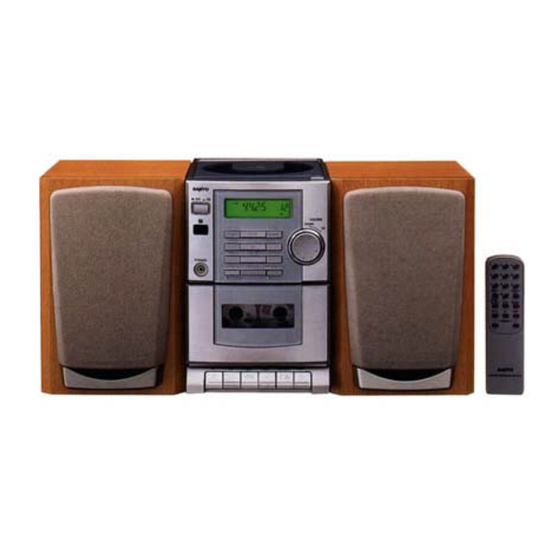
Micro Component System
AM : 522 - 1710 kHz(9KHz step)
520 - 1710 kHz(10KHz step)
semiconductor laser
DC-DA70
PRODUCT CODE No.
129 573 04 (AU)
129 573 05 (PA)
General
Output power ......................... 4 W x 2 (at 4 ohms, 10% distortion)
Outputs .................................. SPEAKERS : 4 ohms
Power requirements ............... AC 230 - 240 V, 50 Hz (AU)
Power consumption ............... 19 W
Dimensions (W x H x D) ........ Approx. 140 x 210 x 200 mm
Weight .................................... Approx. 2.2 kg
Speaker system
Type ....................................... Full range bass reflex
Drivers ................................... 10 cm cone type
Maximum
power-handling capacity ..... 6 W (peak)
Nominal impedance ............... 4 ohms
Dimensions (W x H x D) ........ Approx. 140 x 210 x 184 mm
Weight .................................... Approx. 1.2 kg (per speaker)
Specifications subject to change without notice.
REFERENCE No.
FILE NO.
(AU)
(PA)
PHONES : 8 - 32 ohms
AC 110-120V/220-240V,
50/60Hz (PA)
SM
5810135
Table of Contents

Related Manuals for Sanyo DC-DA70

Summary of Contents for Sanyo DC-DA70
- Page 1 FILE NO. Service Manual DC-DA70 Micro Component System (AU) (PA) PRODUCT CODE No. SPECIFICATIONS 129 573 04 (AU) 129 573 05 (PA) Tuner General Reception frequency ....FM : 87.5 - 108.0 MHz Output power ......4 W x 2 (at 4 ohms, 10% distortion) AM : 522 - 1710 kHz(9KHz step) Outputs ........
-
Page 2: Laser Beam Safety Precaution
Clean a lens with swab of the cotton which moistened it with alcohol, cleaning paper or cleaning disc appointed. Specified cleaning disc : LC-1 (Part code : 645 026 1961 ..manufactured by SANYO.) Show a clean procedure in the following in reference by swab of cotton. -
Page 3: Tape Adjustments
CD PLAYER ADJUSTMENTS (2) Checking the "eye" pattern (RF) 1. Switch "ON" the POWER. OSCILLOSCOPE 2. Connect an oscilloscope to TP1 (RF) and TP4 (VC). 3. Load the test disc. (VC) 4. Press the PLAY button. 5. Check to be sure that the "eye" pattern is at the center of waveform and that the diamond shape is clearly defined. -
Page 4: Tuner Adjustments
TUNER ADJUSTMENTS • Use a plastic screw driver for adjustments. • MODE : ST (Stereo) • Speaker impedance : 6 ohm • TUNING FM : 87.5 - 108.0MHz CT211 AM : 522 - 1710KHz L2204 VT TEST J2403 L2205 T2002 T2001 TP22 J2409... -
Page 5: Exploded View (Cabinet & Chassis)
EXPLODED VIEW (CABINET & CHASSIS) - 4 -... -
Page 6: Parts List
PARTS LIST PRODUCT SAFETY NOTICE EACH PRECAUTION IN THIS MANUAL SHOULD BE FOLLOWED DURING SERVICING. COMPONENTS IDENTIFIED WITH THE IEC SYMBOL IN THE PARTS LIST AND THE SCHEMATIC DIAGRAM DESIGNATED COMPONENTS IN WHICH SAFETY CAN BE OF ! ! ! SPECIAL SIGNIFICANCE. - Page 7 PARTS LIST AMPLIFIER P.W.BOARD ASSY REF.NO. PART NO. DESCRIPTION Q4830 405 004 5103 TR 2SA608-G-SPA REF.NO. PART NO. DESCRIPTION 405 006 1806 TR 2SA933S-R 614 310 4094 ASSY,PWB,AMP,AMP-TU 405 006 1905 TR 2SA933S-S (AU) (Only Initial) 405 004 4601 TR 2SA608-F-SPA 614 310 4919 ASSY,PWB,AMP,AMP-TU 405 143 6504 TR KTA1267-GR (PA) (Only Initial)
- Page 8 PARTS LIST REF.NO. PART NO. DESCRIPTION FRONT P.W.BOARD ASSY R4750 401 038 0800 MT-GLAZE 22K JA 1/10W REF.NO. PART NO. DESCRIPTION R4751 401 038 0800 MT-GLAZE 22K JA 1/10W 614 310 4100 ASSY,PWB,FRONT (Only Initial) R4752 402 071 1304 FUSIBLE RES 2.2 JA 1/4W ! ! ! BR601 614 307 2164 HOLDER,LCD...
- Page 9 PARTS LIST REF.NO. PART NO. DESCRIPTION REF.NO. PART NO. DESCRIPTION R6501 401 037 5400 MT-GLAZE 1K JA 1/10W Q1401 405 009 5306 TR 2SB927-T ! ! ! R6502 401 037 5400 MT-GLAZE 1K JA 1/10W 405 009 5207 TR 2SB927-S ! ! ! R6905 401 037 5202 MT-GLAZE 100 JA 1/10W...
- Page 10 PARTS LIST REF.NO. PART NO. DESCRIPTION REF.NO. PART NO. DESCRIPTION CT211 645 032 5663 TRIMMER,7PF R2201 401 037 5202 MT-GLAZE 100 JA 1/10W D2002 407 157 8109 VARACTOR DI SVC211-B R2205 401 038 9308 MT-GLAZE 68K JA 1/10W D2003 407 157 8109 VARACTOR DI SVC211-B R2206 401 038 0701 MT-GLAZE 2.2K JA 1/10W D2004...
- Page 11 PARTS LIST TAPE MECHANISM (TM-DA70TN-SH... Only Initial) REF.NO. PART NO. DESCRIPTION TM01 614 309 7976 ASSY,MECHA,TM-DA70TN-SH TM01 645 041 3025 R.P HEAD TM03 TM02 TM02 645 009 1612 PINCH ROLLER ARM ASSY TM03 645 033 8625 E.HEAD 6PA TM04 645 009 1766 RF BELT TM05 645 033 3415 MAIN BELT TM06...
-
Page 12: Ic Block Diagram & Description
IC BLOCK DIAGRAM & DESCRIPTION IC211 LA1844ML ( Tuner System) IC201 LA1186N ( FM Front End) RF.AMP DECODER PILOT BUFF ANTI-BIRDIE CANCEL P-DET STEREO φ LEVEL AM/FM COMP S-CURVE BUFF PILOT π 304kHz 19k∠ 19k∠ TUNING DRIVE IC601 LC72336-9921 ( Micro Processor) MICOM NAME PIN NO. - Page 13 IC BLOCK DIAGRAM & DESCRIPTION IC101 LA9241M (Servo Signal Processor) IC410 BA3314 ( MD Rec. Amplifier) Vcc1 BH1 PH1 VR REF1 Vcc2 DRF CE DAT CL CLK 54 53 RF DET FIN2 FIN1 DGND ˚-com INTER FACE RFS- RF Amp RFSM TESI T.SERVO &...
- Page 14 IC BLOCK DIAGRAM & DESCRIPTION IC602 LC78622E (Digital Signal Processor) No. Pin Name I/O Function No. Pin Name I/O Function DEFI I Input terminal for detect signal of defect TEST3 I Test pin. I Input terminal for test. TEST4 I Test pin. O The phase comparison output terminal for - Non connection.
- Page 15 SCHEMATIC DIAGRAM (TUNER (AU) This is a basic schematic diagram. - 14 - - 15 -...
- Page 16 SCHEMATIC DIAGRAM (TUNER (PA) This is a basic schematic diagram. - 18 - - 19 -...
- Page 17 SCHEMATIC DIAGRAM (AMP (AU) This is a basic schematic diagram. - 22 - - 23 -...
- Page 18 SCHEMATIC DIAGRAM (AMP (PA) This is a basic schematic diagram. - 26 - - 27 -...
- Page 19 SCHEMATIC DIAGRAM (FRONT) This is a basic schematic diagram. - 30 - - 31 -...
- Page 20 SCHEMATIC DIAGRAM (CD) IC103 is changed from the units with serial number M0403001(AU) , M0402001(PA). This schematic diagram is for units with smaller serial number than M0403001(AU) , M0402001(PA). Please refer to the schematic diagram on the page 34-35 for the units with serial number M0403001(AU) , M0402001(PA) onward. Please see the wiring diagram on the page 38.
- Page 21 SCHEMATIC DIAGRAM (CD) IC103 is changed from the units with serial number M0403001(AU) , M0402001(PA). This schematic diagram is for units with serial number M0403001(AU) , M0402001(PA) onward. Please refer to the schematic diagram on the page 32-33 for the units with smaller serial number than M0403001(AU) , M0402001(PA). Please see the wiring diagram on the page 36-37.
-
Page 22: Wiring Diagram (Cd)
WIRING DIAGRAM (CD) IC103 is changed from the units with serial number M0403001(AU) , M0402001(PA). This wiring diagram is for units with smaller serial number than M0403001(AU) , M0402001(PA) . Please refer to the wiring diagram on the page 36-37 for the units with the serial number M0403001(AU) , M0402001(PA) onward. - 38 -... - Page 23 WIRING DIAGRAM (LED & POWER) LED P.W.BOARD POWER TRANSFORMER P.W.BOARD This wiring diagram is for AU version. This wiring diagram is for PA version. - 39 -...
-
Page 24: Voltage Table
VOLTAGE TABLE IC101 LA9241M UNIT:V Pin No. Voltage Pin No. Voltage 0.05 Pin No. Voltage 0.02 0.08 0.25 0.01 0.02 0.17 0.84 0.84 IC102 LC78622 UNIT:V Pin No. Voltage 0.02 0.16 0.02 0.05 Pin No. Voltage 0.01 0.01 Pin No. Voltage 0.23 0.01... - Page 25 IC BLOCK DIAGRAM & DESCRIPTION - 41 -...
-
Page 26: Wiring Connection
WIRING CONNECTION TUNER P.W.B CN201 L-CH R-CH SPEAKER SPEAKER CN202 AM LOOP (17P) ANT. CN203 (1P) ANT. AMP P.W.B BOARD TO BOARD CN491 CN402 (12P) (2P) CN401 LED P.W.B (2P) CN421 CN490 PHONES (8P) LCD60 CN406 CN603 CN602 (4P) (17P) (2P) CN601 CN405... -
Page 27: Fl Display Description
FL DISPLAY DESCRIPTION PAD NO. COM2 PAD NO. COM1 COM2 COM3 COM1 COM3 COM1 COM2 COM3 MONO JAZZ ROCK CLASSIC PLAY SANYO Technosound Co., Ltd. Jun. / '00 /1550 BB Printed in Japan Osaka, Japan... - Page 28 WIRING DIAGRAM (TUNER (AU) - 16 - - 17 -...
- Page 29 WIRING DIAGRAM (TUNER (PA) - 20 - - 21 -...
- Page 30 WIRING DIAGRAM (AMP (AU) - 24 - - 25 -...
- Page 31 WIRING DIAGRAM (AMP (PA) - 28 - - 29 -...
- Page 32 WIRING DIAGRAM (CD & FRONT) IC103 is changed from the units with serial number M0403001(AU) , M0402001(PA). This wiring diagram is for units with serial number M0403001(AU) , M0402001(PA) onward. Please refer to the wiring diagram on the page 38 for the units with the smaller serial number than M0403001(AU) , M0402001(PA). - 36 - - 37 -...