Table of Contents
READ AND SAVE THESE INSTRUCTIONS
Ceiling Fan Owner's Manual
Emerson Electric Customer Service - 8 a.m. - 6 p.m., Eastern, Monday-Friday
Part No. F40BP75000000
Revision: 150108
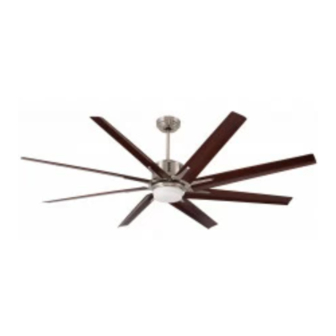
AIRA ECO™
72" Damp Location
Model Numbers
CF985BS00
Brushed Steel
CF985ORB00
Oil Rubbed Bronze
Net Weight:
Questions, problems, missing parts: Before returning to the store call
1-800-654-3545
www.emersonfans.com
32.6
Lbs.
• Español - página 31
• Français - page 61
Form No. BP7500
E.T.L. Model No.: CF985
Table of Contents

Related Manuals for Emerson AIRA ECO CF985BS00


Summary of Contents for Emerson AIRA ECO CF985BS00
- Page 1 32.6 Net Weight: Lbs. Questions, problems, missing parts: Before returning to the store call Emerson Electric Customer Service - 8 a.m. - 6 p.m., Eastern, Monday-Friday • Español - página 31 1-800-654-3545 • Français - page 61 Part No. F40BP75000000 Form No.
-
Page 2: Table Of Contents
WARNING: To avoid fire, shock or injury, do not use an Emerson or any other brand of control not specifically 3. Do not put anything into the fan blades while they are approved for this fan. -
Page 3: Unpacking Instructions
Emerson Electric Light Fitter Co. Substitution of parts or accessories not designated Glass Bowl for use with this product by Emerson Electric Co. could result in personal injury or property damage. Removable No-Light Cover Plate Blade Flanges... -
Page 4: Tools Needed For Assembly
Turning off wall switch is not sufficient. To avoid possible electrical shock, be sure electricity is turned off at the Please call Emerson technical support main fuse box before wiring. All wiring must be in 1-800-654-3545 if you have any questions about accordance with National and Local codes and the ceiling installation and operation of this ceiling fan. -
Page 5: Ceiling Fan Assembly
3. Ceiling Fan Assembly WARNING Turning off wall switch is not sufficient. To avoid possible Disconnect electrical power to the branch circuit at the electrical shock, be sure electricity is turned off at the circuit breaker or fuse box before attempting to install the main fuse box before wiring. - Page 6 3. Ceiling Fan Assembly (Continued) Loosen the two setscrews in the motor coupling. Place the 6” downrod into the motor coupling, aligning the HAIRPIN 6" DOWNROD clevis pin holes in the downrod with the holes in the motor CLIP coupling (Figure 3). CLEVIS The clevis pin must go through the holes in the motor coupling and the holes in the downrod.
- Page 7 3. Ceiling Fan Assembly (Continued) 6" DOWNROD Route the 80” black and white motor leads through the ceiling cover (Figure 6). Place the ceiling cover over the downrod. Be sure both the CEILING COVER ceiling cover and the coupling cover are oriented correctly (Figure 6).
-
Page 8: How To Hang Your Ceiling Fan
4. How to Hang Your Ceiling Fan WARNING CEILING The fan must be hung with at least 7' of clearance from floor to blades (Figure 9). AT LEAST FLOOR Figure 9 WARNING The outlet box and joist must be securely mounted and capable of supporting at least 50 lbs. - Page 9 4. How to Hang Your Ceiling Fan (Continued) Remove the socket head cap screw with the hex wrench (supplied in the parts bag) from the retaining strap to the OUTLET hanger bracket (Figure 11); retain the socket head cap screw for future use. RETAINING STRAP Swing open the retaining strap as shown in Figure 11.
-
Page 10: How To Wire Your Ceiling Fan
Co. Substitution of parts or accessories not designated accordance with National and Local codes and the ceiling for use with this product by Emerson Electric Co. could fan must be properly grounded as a precaution against result in personal injury or property damage. - Page 11 5. How to Wire Your Ceiling Fan (Continued) Securely connect the fan motor white wire to the supply white (neutral) wire using wire connector supplied SUPPLY WHITE (Figure 15). (NEUTRAL) LISTED WIRE CONNECTOR FAN MOTOR WHITE WIRE Figure 15 Securely connect the fan motor black wire to the supply black (hot) wire using wire connector supplied FAN MOTOR (Figure 16).
-
Page 12: Installation Of The Ceiling Cover
6. Installation of the Ceiling Cover Screw the two threaded studs (supplied) into the tapped holes in the hanger bracket (Figure 18) HANGER BRACKET THREADED STUD (2) Figure 18 Lift the ceiling cover up to the threaded studs and turn until studs protrude through the holes in the ceiling cover (Figure 19). -
Page 13: Installation Of The Fan Blades
7. Installation of the Fan Blades Remove the shipping spacers and the spacer attachment screws from the motor before installation of blade assemblies (Figure 20). Discard the spacers and spacer screws. MOTOR ASSEMBLY SHIPPING SPACER (4) Figure 20 SHIPPING SPACER SCREW (4) #8-32 x 8mm WASHER WARNING HEAD BLADE SCREW (5) -
Page 14: Installation Of Downlight Assembly
8. Installation of Downlight Assembly Remove one of the three #6-32 x 3/8” truss head screws with lockwashers from the fan motor assembly (Figure 23). Retain the screw for future installation. Loosen the other two screws several turns. WARNING To avoid possible fire or shock, do not pinch wires between the fan motor assembly and the light fitter housing. - Page 15 8. Installation of Downlight Assembly (Continued) Connect the white wire from the fan motor assembly to the white wire of the light fitter (Figure 25). Connect the black wire from the fan motor assembly to the FAN MOTOR ASSEMBLY black wire of the light fitter (Figure 25). WHITE WIRE FAN MOTOR ASSEMBLY...
- Page 16 8. Installation of Downlight Assembly (Continued) If using the No-light Cover Plate, skip this section and go to Section 9. Light Fitter Light Bulb Installation: If light fitter is to be used as a down light, screw in two 50-watt (maximum) mini-candelabra base halogen bulbs CAUTION: To avoid risk of burns or other injury, (supplied) into the light fitter sockets (Figure 28).
-
Page 17: Optional Installation Of No-Light Cover Plate
9. Optional Installation of No-Light Cover Plate If NO light fitter is to be used, Installation of the No-Light Cover Plate: Remove the glass bowl from the light fitter by turning the bowl counter-clockwise. Store glass bowl in a secure place for future use (Figure 30). -
Page 18: Wall Control Procedures
Code switches in the transmitter may be set in 32 different positions. If your fan and light turn on and Your Emerson Ceiling Fan/Light Control consists of off without using your control, you may be getting SW605 wall mounted transmitter and a receiver located interference from other remote units such as garage inside the motor assembly. -
Page 19: Wall Control Installation
11. Wall Control Installation SINGLE-POLE INSTALLATION WARNING CAUTION: To reduce the risk of electrical shock, Turning off wall switch is not sufficient. To avoid possible disconnect the electrical supply circuit before electrical shock, be sure electricity is turned off at the main fuse or circuit breaker box before wiring. - Page 20 11. Wall Control Installation (Continued) 11.3 SW605 FAN/LIGHT SCREWS (2) WALL BOX Before installing the SW605 wall control, place the SW605 WALL CONTROL wall control in “OFF” mode by pushing “ON/OFF” switch to 11.4 the “OFF” position. Connect one black wire of the SW605 wall control to the “hot”...
- Page 21 11. Wall Control Installation (Continued) 3-WAY INSTALLATION (One fan controlled by two different SW605 wall controls) (See Figures 35 and 36.) SW605 FAN/LIGHT WALL WARNING CONTROL Turning off wall switch is not sufficient. To avoid possible BLACK electrical shock, be sure electricity is turned off at the main fuse or circuit breaker box before wiring.
- Page 22 11. Wall Control Installation (Continued) OPTIONAL 3-WAY WIRING DIAGRAM: STANDARD WIRING FOR EXISTING NEW CONSTRUCTION 3-WAY CONTROLS Requires purchase of an additional SW605 Wall Control EXISTING NOTE: Retrofit 3-way installations are likely to include WALL CONTROL two traveler wires between the two wall boxes. In new construction, only one traveler wire Is required (See Figure 36).
-
Page 23: Programming Fan Control
12. Programming the Receiver Operating Frequency & High Speed Conditioning of Fan Control -- Important - Read This Section Carefully and Follow the High Speed Conditioning Instructions Closely -- 12.2 PROGRAMMING THE RECEIVER OPERATING FREQUENCY & HIGH SPEED CONDITIONING OF FAN CONTROL The fan will run for approximately 2 minutes in the upward IMPORTANT: Ceiling fan blades MUST be installed direction then reverse direction to down flow and run an... -
Page 24: Using Your Ceiling Fan
13. Using Your Ceiling Fan WARNING USING YOUR CEILING FAN Fan installation must be completed, including the installation of the fan blades, before testing the SW605 wall control. Your SW605 wall control has full control of your fan and light (Figure 37). NOTE: Prior to operation of the fan and light from the wall control, set the fan speed to HIGH ( .. -
Page 25: Maintenance
Downrod Extension Kits - See your local Emerson dealer, Co. Substitution of parts or accessories not designated the Emerson website www.emersonfans.com or the for use with this product by Emerson Electric Co. could result in personal injury or property damage. Emerson ceiling fan catalog. -
Page 26: Repair Parts
17. Repair Parts PARTS BAG E.T.L. Model No.: CF985... - Page 27 17. Repair Parts Listing Model Numbers No. Description CF985BS00 CF985ORB00 Hanger Pack Assembly, Consisting of: 761655-27 761655-5 Slope Ceiling Hanger Bracket — — Hanger Ball / 6” Downrod Assembly — — Ceiling Cover 764663-BS 764663-ORB Coupling Cover 764664-BS 764664-ORB Light Fitter Housing 764673-BS 764673-ORB Light Fitter...
-
Page 28: Trouble Shooting
18. Trouble Shooting WARNING: FOR YOUR OWN SAFETY TURN OFF POWER AT FUSE BOX OR CIRCUIT BREAKER BEFORE TROUBLE SHOOTING YOUR FAN. TROUBLE PROBABLE CAUSE SUGGESTED REMEDY 1. Fan will not start. 1. Fuse or circuit breaker blown. 1. Check main and branch circuit fuses or circuit WARNING: Make sure main power is breakers. -
Page 29: Ceiling Fan Limited Warranty
Emerson Ceiling Fan. Once we have processed your return authorization request, we will provide you with a postage paid return label which should be affixed to the Emerson Ceiling Fan package you ship to the address listed at the end of this limited warranty. The return label will be sent to the mailing address you provide to us by phone. - Page 30 Air Comfort Products DIVISION OF EmErSON ElEctrIc cO. 8100 W. Florissant • St. louis, mO 63136 Questions, problems, missing parts: Before returning to the store call Emerson Electric Customer Service 8 a.m. - 6 p.m., Eastern, Monday-Friday 1-800-654-3545 www.emersonfans.com Retain this manual for future use.