
Related Manuals for NEC EV-K0-HCD


Summary of Contents for NEC EV-K0-HCD
- Page 1 Hardware User’s Manual EV-K0-HCD Evaluation Kit ©May 2008. NEC Electronics America, Inc. Printed in USA. All rights reserved. Document no. 51069...
-
Page 2: Table Of Contents
EV-K0-HCD Evaluation Kit User’s Manual Contents Introduction ............................ 1 Contents................................. 1 Features ................................. 1 Hardware ............................3 Power Supply ............................... 4 LED Drivers..............................4 On-board LUXEON Rebel LEDs......................4 Future Lighting Solutions LED Board ....................5 LED Light Engine Connectors......................... 5 RS-485/DMX-512 Interface ........................ -
Page 3: Introduction
EV-K0-HCD Evaluation Kit User’s Manual 1. INTRODUCTION The EV-K0-HCD evaluation kit for NEC Electronics’ highly integrated, general-purpose µPD78F8024 microcontroller (MCU) with high-current drive allows you to demonstrate the MCU’s capabilities and easily develop intelligent code for emerging high-power LED lighting applications. Compact yet flexible... - Page 4 EV-K0-HCD Evaluation Kit User’s Manual • Expansion IO connector • On-board temperature sensor • On-board ambient light sensor • DIP switch for board configurations • Reset switch for uPD78F8024 device reset...
-
Page 5: Hardware
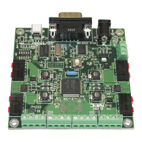
EV-K0-HCD Evaluation Kit User’s Manual 2. HARDWARE The EV-K0-HCD board measures 3.15 × 3.15 inches or 80 × 80 millimeters (mm). This small form factor is enabled by the use of components such as inductors that are small in size thanks to the µPD78F8024 MCU’s constant-current drives with high switching frequency. -
Page 6: Power Supply
On-board LEDs There are four LUXEON Rebel high-power LEDs mounted on the back of the EV-K0-HCD board, one red (R), one green (G), one blue (B) and one white (W). By default, the board is set to drive the LEDs... -
Page 7: Future Lighting Solutions Led Board
Figure 2. Driving Future Lighting Solutions LED Boards LED Light Engine Connector The EV-K0-HCD board has four LED light engine connectors (refer to J5, J6, J7 and J8 in the schematics) to the 4-pin terminal block. The following table describes the function of each pin. -
Page 8: Rs-485/Dmx-512 Interface
Figure 3. Driving the Dialight Light Engines RS-485/DMX-512 Interface The EV-K0-HCD board supports DMX-512 protocol over RS-485 using the MCU’s UART0 port. The RS-485/DMX-512 connector is a 3-pin terminal block connector that accepts up to 24 American Wire Gauge (AWG) wires. -
Page 9: Rs-232 Interface
Not Connected Expansion IO Connector A dual-row 10-pin header footprint in 2mm-pitch is available on the EV-K0-HCD board (refer to CN3 in the schematics), the uPD78F8024 device’s UART0/CSI and I2C signals are pulled out on this connector. The following table shows the pin out connections. -
Page 10: Ambient Light Sensor
µPD78F8024 MCU’s A/D converter input. To connect to it, place DIP switch (SW1) position 6 in the “ON” position. 2.12 DIP Switch The EV-K0-HCD board uses a 6-position DIP switch (SW1) for configuration purposes. The following table shows the various configuration options. rd Configuration Options... -
Page 11: Software
EV-K0-HCD Evaluation Kit User’s Manual 3. SOFTWARE The EV-K0-HCD board is preprogrammed with a demonstration code that cyclically dims the four on-board high-power LEDs. You can also use the Applilet EZ software tool generate demonstration programs with different dimming control patterns. Refer to the Applilet EZ Software User’s Manual and EV-... -
Page 12: Appendix A. Schematics
EV-K0-HCD Evaluation Kit User’s Manual Appendix A. Schematics... - Page 13 EV-K0-HCD Evaluation Kit User’s Manual...
-
Page 14: Appendix B. Bill Of Materials
EV-K0-HCD Evaluation Kit User’s Manual Appendix B. Bill of Materials Name Manufacturer / Part # Qty. Description HCD/LED MCU NEC Electronics / µPD78F8024GK 64-pin LQFP U2, U3 MOSFETs NEC Electronics / µPA2756GR 8-pin SOP, dual-N FET Voltage regulator TI / UA78M05CDCYR... - Page 15 EV-K0-HCD Evaluation Kit User’s Manual Name Manufacturer / Part # Qty. Description SB1, SB2, SB3 Solder bridge 0603 footprint C21, C22 Capacitor Kemet / C0603C180J5GACTU 18 pF, 0603 C3, C24, C25 Capacitor Kemet / C0603C105K8PACTU 1 µF, 10V, 0603 C4, C5, C6, C7...
-
Page 16: Appendix C. Board Assembly
EV-K0-HCD Evaluation Kit User’s Manual Appendix C. Board Assembly Figure 4. Top Assembly Figure 5. Bottom Assembly... -
Page 17: Appendix D. Board Layout
EV-K0-HCD Evaluation Kit User’s Manual Appendix D. Board Layout Figure 6. Top Layer Figure 7. Layer 1... - Page 18 EV-K0-HCD Evaluation Kit User’s Manual Figure 8. Layer 2 Figure 9. Bottom Layer...
- Page 19 No part of this document may be copied or reproduced in any form or by any means without prior written consent of NEC Electronics. NEC Electronics assumes no responsibility for any errors that may appear in this document.