Table of Contents
1. Application Model
• CLX-925x/935x series
• SCX-8x30/8x40 series
2. Stack Capacity (A4/LT 80gsm)
• CLX-FIN40S : 1,000 sheets (Main) / 250 sheets (Top)
• CLX-FIN40L : 3,000 sheets (Main) / 250 sheets (Top)
3. Staple (Finisher)
• Capacity : 50 sheets (90gsm)
• Cartridge Capacity : 5,000 clinching/cartridge
Service Manual
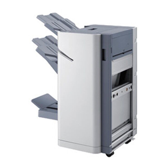
Finisher Service Manual
CLX-FIN40S / CLX-FIN40L
4. Staple (Booklet maker)
• Staple/Fold capacity : 15 sheets
• Cartridge Capacity : 1,000 clinching/cartridge)
Table of Contents

Related Manuals for Samsung CLX-FIN40S

Summary of Contents for Samsung CLX-FIN40S
- Page 1 • SCX-8x30/8x40 series • Cartridge Capacity : 1,000 clinching/cartridge) 2. Stack Capacity (A4/LT 80gsm) • CLX-FIN40S : 1,000 sheets (Main) / 250 sheets (Top) • CLX-FIN40L : 3,000 sheets (Main) / 250 sheets (Top) 3. Staple (Finisher) • Capacity : 50 sheets (90gsm)
- Page 2 GSPN (Global Service Partner Network) North America : service.samsungportal.com Latin America : latin.samsungportal.com CIS : cis.samsungportal.com Europe : europe.samsungportal.com ⓒ Samsung Electronics Co.,Ltd. April. 2010 China : china.samsungportal.com Printed in Korea. Asia : asia.samsungportal.com Mideast & Africa : mea.samsungportal.com VERSION NO. : 1.00...
-
Page 3: Table Of Contents
1.8 Hole Punch Specif cations ……………………………………… 1-14 1.9 Booklet Maker Specif cations …………………………………… 1-16 chapter 2 System Confi guration 2.1 Front sectional view ……………………………………………… 2-1 a) CLX-FIN40S ……………………………………………………… 2-1 b) CLX-FIN40L ……………………………………………………… 2-2 2.2 Paper path ………………………………………………………… 2-4 a) CLX-FIN40S ……………………………………………………… 2-4 b) CLX-FIN40L ……………………………………………………… 2-5 2.3 Layout of electrical parts …………………………………………... - Page 4 Contents chapter 3 Replacement procedure 3.1 General precautions on disassembly …………………………… 3-1 3.2 CLX-FIN40S disassembly ……………………………………… 3-2 3.2.1 AS-FRAME UNIT …………………………………………… 3-2 3.2.2 AS-COMPILER EJECTOR ………………………………… 3-17 3.2.3 AS-STAPLER ENDFENCE ………………………………… 3-28 3.2.4 ENDFENCE UNIT …………………………………………… 3-34 3.2.5 Finisher exit sensor ………………………………………… 3-35 3.2.6 AS-BELT ………………………………………………………...
- Page 5 General Precautions The service should be done by a qualified service technician. 1. Before servicing or maintenance work, be sure to turn off and unplug the equipment first. 2. Be sure to fix and plug in the power cord securely after the service so that no one trips over it. 3.
-
Page 6: General Specif Cations
1. Specification 1. Specifications 1.1 General Specifications Item CLX-FIN40S CLX-FIN40L - Color Model 876 x 610 x 1074 mm Size W x D x H 696 x 610 x 536 mm - Mono Model 876 x 610 x 1018 mm - Color Model : 70.2 Kg... -
Page 7: Finisher Specif Cations
1. Specification 1.2 Finisher Specifications Item CLX-FIN40S CLX-FIN40L 25~50 25~50 Speed Feed Velocity 112.5~245 mm/sec 112.5~245 mm/sec Paper alignment Center Center Configuration Hanging type Stand alone Non Staple 0 Skip 0 Skip Skips Pitch Staple Minimized skip Minimized skip Main... -
Page 8: Booklet Maker Specif Cations
60 ~ 120 gsm Cover sheet = Max. 216 gsm Staple/Fold Capacity 15 sheets 1 sheet folding mode V folding Max. 216 gsm Tray Capacity 20 sets / 15 sheets Staple Cartridge Capacity 1,000 clinching/cartridge Service Manual SAMSUNG ELECTRONICS CLX-FIN40S/CLX-FIN40L... - Page 9 4.5×6.4 Statement 140X216 5.5X8.5 148X210 5.8X8.3 C5 Env 162×229 6.4×9.0 B5(ISO) 176×250 6.9×9.8 B5(JIS) 182X257 6.9X9.8 Executive 184X267 7.3X10.5 195X270 7.7X10.6 210X297 8.3X11.7 Legal 216X356 8.5X14 Letter 216X279 8.5X11 Folio 216X330 8.5X13 Oficio 215.9×342.9 8.5×13.5 Service Manual SAMSUNG ELECTRONICS CLX-FIN40S/CLX-FIN40L...
- Page 10 279X216 11X8.5 297X210 8.3X11.7 No 9 Env 98X225 3.9X8.9 Monarch 98.4×190.5 3.9×7.5 PostCard 101.6×152.4 4.0×6.0 105X148 4.1X5.8 No 10 Env 105×241 4.1×9.5 DL Env 110×220 4.3×8.7 C6 Env 114×162 4.5×6.4 Statement 140X216 5.5X8.5 148X210 5.8X8.3 Service Manual SAMSUNG ELECTRONICS CLX-FIN40S/CLX-FIN40L...
- Page 11 Oficio 215.9×342.9 8.5×13.5 229×324 9.1X12.8 Tabloid 254X374 10 X14.7 257X364 10X14.3 270X390 10.6X15.4 Ledger 279X432 11X17 297X420 11.7X16.5 Tabloid 304.8×457.2 12×18 Extra SRA3 320×450 12.6×17.7 W 89-312 ~ W3.5-12.3 ~ Custom L 140-457.2 L 5.5-18 Service Manual SAMSUNG ELECTRONICS CLX-FIN40S/CLX-FIN40L...
- Page 12 Skew : Finisher must be able to control ‘skew’ of the sheet received from the IOT. The skew must be less than 1% of the length of the paper received from IOT main body (feeding direction). Service Manual SAMSUNG ELECTRONICS CLX-FIN40S/CLX-FIN40L...
- Page 13 Thick Cardstock (170~216 g/㎡) Thin Glossy (106~169 g/㎡) Thick Glossy (170~216 g/㎡) Envelope(75~90 g/㎡) Transparency (138~146 g/㎡) Labels (120~150 g/㎡) Tab* *The tab must be positioned on the lead edge as it enters the finisher. Service Manual SAMSUNG ELECTRONICS CLX-FIN40S/CLX-FIN40L...
- Page 14 The Main Tray must accommodate following capacities. Slight diminishing of the capacity due to buildup staples can be tolerated, however jamming caused by the buildup blocking the path of ejecting papers must be prevented. Stack Capacity Paper Dimension (80gsm) CLX-FIN40S CLX-FIN40L Under 70,000 mm 1,000 3,000...
-
Page 15: Mode Feature
Booklet Maker Mode : A Dual Stapling must be possible at V-folding line of the paper (that can cover 15 sheets, or a 216gsm cover + fourteen 80gsm sheets, etc) that goes through the Booklet maker. The folding is positioned at the centerline of the paper path. 1-10 Service Manual SAMSUNG ELECTRONICS CLX-FIN40S/CLX-FIN40L... -
Page 16: Staple Set Specif Cations
A±2 mm Direction Direction of Feed of Feed D±2 mm D±2 mm Adjustable amount Adjustable amount Dimension Nominal Dimension Nominal Remark Remark 6.0mm 5.0mm 5.0mm 6.0mm 5.0mm 5.0mm Service Service Mode Mode 6.0mm 6.0mm 1-11 Service Manual SAMSUNG ELECTRONICS CLX-FIN40S/CLX-FIN40L... - Page 17 1. Specification Dual Direction A = (Paper size_STS/2)-79.5 of Feed Depend on paper size D±2 mm A±2 mm B±2 mm Adjustable amount Dimension Nominal Remark See block 5.0mm Service 6.0mm 1.0mm 1.0mm Mode 148mm 1-12 Service Manual SAMSUNG ELECTRONICS CLX-FIN40S/CLX-FIN40L...
- Page 18 When the user puts in more than the number of papers that can clinched together, the clinching will not take place. Instead, the user will be required to select ‘sub-set mode’ or ‘divide clinching’ on the GUI. 1-13 Service Manual SAMSUNG ELECTRONICS CLX-FIN40S/CLX-FIN40L...
-
Page 19: Hole Punch Specif Cations
80 ±0.5 mm 6.5 ±0.5 6.5 ±0.5 8± 0.5 mm 8± 0.5 mm Ф Ф ±5.0mm(0.1mm/step) ±5.0mm(0.1mm/step) ±5.0mm(0.1mm/step) ±5.0mm(0.1mm/step) α = (Paper Size_STS – 3C) ÷ 2 β = (Paper Size_STS - 2d) ÷ 2 1-14 Service Manual SAMSUNG ELECTRONICS CLX-FIN40S/CLX-FIN40L... - Page 20 γ = (Paper Size_STS - c - 2d) ÷ 2 Ω = (Paper Size_STS - c) ÷ 2 * The “X” dimension can be adjust under both service mode and user mode, but the “Z” dimension can be adjust only service mode. 1-15 Service Manual SAMSUNG ELECTRONICS CLX-FIN40S/CLX-FIN40L...
-
Page 21: Booklet Maker Specif Cations
358.5mm ≤ L < 426.0mm ± 5.0mm (0.1mm/step) 426.0mm ≤ L ± 5.0mm (0.1mm/step) * The “C” dimension can be adjust under both service mode and user mode. And the staple position follow that value of “C”. 1-16 Service Manual SAMSUNG ELECTRONICS CLX-FIN40S/CLX-FIN40L... - Page 22 Y (as measured on the inside of 1.5mm 3.0mm 2.1mm 3.6mm the booklet) AZAP 1.9.3 Booklet Staple Leg Quality B < 1.2 mm A < B A and C < 0.4 mm D < 0.4 mm 1-17 Service Manual SAMSUNG ELECTRONICS CLX-FIN40S/CLX-FIN40L...
-
Page 23: System Confi Guration
2. System Configuration 2. System Configuration 2.1 Front sectional view a) CLX-FIN40S Sensor Feed Roller Name Name Trans Bridge Input Sensor Top exit roller Trans Bridge Exit Sensor Top middle roller Finisher Input Sensor Finisher Compile Exit roller Finisher Compile Exit Sensor... -
Page 24: B) Clx-Fin40L
Finisher Top Exit Sensor Finisher Compile Exit Sensor Booklet Compile Exit Sensor Paper Present Sensor Booklet Compile Present Sensor Paper Height Sensor Booklet Folding Exit Sensor Stacker Upper Limit Emitting Sensor BM Set Detect Sensor Service Manual SAMSUNG ELECTRONICS CLX-FIN40S/CLX-FIN40L... - Page 25 BM Compile Cover TB Middle-1 Roller BM Stopper Cover TB Entrance Roller BM Roller Knob Finisher Trans Roller BM Folding Roller Knob BM Compile Exit Roller BM Knife Knob BM Folding Roller BM Conveyor Exit Roller Service Manual SAMSUNG ELECTRONICS CLX-FIN40S/CLX-FIN40L...
-
Page 26: Paper Path
2. System Configuration 2.2 Paper path a) CLX-FIN40S Finisher Main Tray - Staple & Punch (Optional) Finisher Top Tray - Punch (Optional) Service Manual SAMSUNG ELECTRONICS CLX-FIN40S/CLX-FIN40L... -
Page 27: B) Clx-Fin40L
2. System Configuration b) CLX-FIN40L Finisher Main Tray - Staple & Punch (Optional) Finisher Top Tray - Punch (Optional) Booklet Conveyor Tray – Folding & Staple Service Manual SAMSUNG ELECTRONICS CLX-FIN40S/CLX-FIN40L... -
Page 28: Layout Of Electrical Parts
2. System Configuration 2.3 Layout of electrical parts a) CLX-FIN40S Part Code Symbol Description Function JC81-07420A AS-SENSOR:KIT5011C Offline Stapler Sensor JC81-07420A AS-SENSOR:KIT5011C Feed Compile Exit Sensor JC81-07420A AS-SENSOR:KIT5011C Feed Top Exit Sensor JC81-03480A PHOTO SENSOR:PS119ED1 Feed Entrance Sensor JC81-07420A AS-SENSOR:KIT5011C... - Page 29 Ejector Motor JC81-07387A AS-MOTOR PM:Z18:HELICAL Extension Tray Motor JC81-07389A AS-MOTOR PM:STAPLER Stapler Sub Moving Motor JC81-07389A AS-MOTOR PM:STAPLER Stapler Main Moving Motor JC81-03473A ASSY:PM MOTOR:Z18 SCU Motor CF10 6802A ASSY:3657 DC MOTOR:S2M14T Stacker Moving Motor Service Manual SAMSUNG ELECTRONICS CLX-FIN40S/CLX-FIN40L...
-
Page 30: B) Clx-Fin40L
2. System Configuration b) CLX-FIN40L Booklet Module See the next page. Service Manual SAMSUNG ELECTRONICS CLX-FIN40S/CLX-FIN40L... - Page 31 JC81-07420A AS-SENSOR:KIT5011C Feed Top Exit Sensor JC81-03480A PHOTO SENSOR:PS119ED1 Feed Entrance Sensor JC81-07420A AS-SENSOR:KIT5011C Diverter Home Sensor JC81-07420A AS-SENSOR:KIT5011C Rear Tamper Home Sensor JC81-07420A AS-SENSOR:KIT5011C Front Tamper Home Sensor JC81-07420A AS-SENSOR:KIT5011C Main Paddle Home Sensor Service Manual SAMSUNG ELECTRONICS CLX-FIN40S/CLX-FIN40L...
- Page 32 Finisher Main PCB JC81-07406A AS-PCB OP Offline Staple OP PCB JC81-07407A AS-PCB STAPLER RELAY Stapler Relay Moving PCB PCB ASSY:STAPLER RELAY FIXED:C- Stapler Relay PCB CF10 8275B CFBM 8200A PCB ASSY:BOOKLET Booklet Main PCB 2-10 Service Manual SAMSUNG ELECTRONICS CLX-FIN40S/CLX-FIN40L...
- Page 33 JC81-08285A AS-JOG MOTOR Front Jog Motor JC81-08275A AS-PM MOTOR:S2M19T Stopper Moving Motor JC81-03479A ASSY:HB MOTOR:S2M19T Booklet Feed Motor JC31-00040A MOTOR BLDC-MAIN Folding Roller Motor JC31-00040A MOTOR BLDC-MAIN Blade Motor JC81-08264A AS-DC MOTOR:2738:S2M12T:PCB Conveyor Motor 2-11 Service Manual SAMSUNG ELECTRONICS CLX-FIN40S/CLX-FIN40L...
-
Page 34: C) Clx-Brg200
2. System Configuration c) CLX-BRG200 (Bridge unit) Symbol Part Code Description Function JC81-03479A ASSY:HB MOTOR:S2M19T Bridge Feed Motor JC81-07420A AS-SENSOR:KIT5011C Bridge Exit Sensor JC81-07420A AS-SENSOR:KIT5011C Bridge Entrance Sensor JC81-07430A AS-PCB BRIDGE Bridge PCB 2-12 Service Manual SAMSUNG ELECTRONICS CLX-FIN40S/CLX-FIN40L... -
Page 35: Function Of Units
2. System Configuration 2.4 Function of units a) CLX-FIN40S Unit Function Frame Unit It is finisher’s main frame and exterior. Stapler Unit This unit is a device used for putting staples in to sheets of paper. Feed Unit This unit transports the paper to the compile & eject unit. -
Page 36: B) Clx-Fin40L
This unit stack papers on the tray. This unit performs paper folding & stapling jobs and transports the Booklet Unit paper to the tray. Conveyor Tray Unit This unit stack papers on the tray. 2-14 Service Manual SAMSUNG ELECTRONICS CLX-FIN40S/CLX-FIN40L... -
Page 37: Block Diagram
This is the board to control the booklet maker module and consists of the micro-controller and driver ICs. • HOLE PUNCH board This is the board to control the hole punch module and consists of the micro-controller and driver ICs. 2-15 Service Manual SAMSUNG ELECTRONICS CLX-FIN40S/CLX-FIN40L... -
Page 38: Plug And Jack Location List
Compiler Upper Motors PJ/5 P/J15 and Sensors P/J16 Paper Path Sensors PJ/4 PJ/3 PJ/2 PJ/1 b) Bridge Drive Board PJ/202 Connector Figure Title Number P/J201 Br idge Interface P/J202 Bridge Motor PJ/203 PJ/201 P/J203 Bridge Sensors 2-16 Service Manual SAMSUNG ELECTRONICS CLX-FIN40S/CLX-FIN40L... - Page 39 Feed Exit Sensor, Tray Paper Sensor, Fold Exit Sensor, Knife Home Sensor P/J7 Gate Home Sensor, Paddle Home Sensor P/J8 K nife Motor P/J9 Fold Motor P/J10 Stap P/J11 Stacker Tray Motor, Stacker Tray Full Sensor 2-17 Service Manual SAMSUNG ELECTRONICS CLX-FIN40S/CLX-FIN40L...
-
Page 40: General Precautions On Disassembly
5. Replace only with authorized components. 6. Do not force plastic-material components. 7. Make sure all components are in their proper positio 8. When disassembling the Bridge and Finisher, B Be careful not to be damaged the connectors Service Manual SAMSUNG ELECTRONICS CLX-FIN40S/CLX-FIN40L... -
Page 41: Clx-Fin40S Disassembly
3. Replaceme nt Procedure 3.2 CLX-FIN40S disassembly 3.2.1 AS-FRAME UNIT 3. Unplug 1 connector. Release the AS- 1. Open the CSP-COVER:DOOR [A]. SENSOR:KIT5011C [C]. Remove 4 screws. And release the CSP- COVER:FRONT. 4. Unplug the connectors and remove 2 screws. - Page 42 5. Pull the CSP:COVER:REAR:TOP [E] to the front COVER:PUNCH:SF [G]. and release it. 8. Remove 4 screws from the top and bottom of th t d b tt the CSP-COVER:REAR [H]. 6. Remove 1 screw. Release the CSP- COVER:DUMMY:PCB [F]. Service Manual SAMSUNG ELECTRONICS CLX-FIN40S/CLX-FIN40L...
- Page 43 11. Unplug the connector and remove 2 screws. 9. Release the CSP-COVER:REAR [H]. Release the SUB ASSY:FEED MOTOR. 12. Unplug 2 connectors and remove 1 screw. 10. Unplug all connectors and remove 4 screws. Release the AS-BELT [J]. Release the PCB ASSY:MAIN:C-FIN. Service Manual SAMSUNG ELECTRONICS CLX-FIN40S/CLX-FIN40L...
- Page 44 15. Remove 1 screw. Release the SUB ASSY 13. Release the DRIVERTER SENSOR [K]. CON SHAFT. 16. Unplug 2 connectors and remove 3 screws. 14. Remove 3 screws. Release the SUB ASSY Release the AS-STACKER MTR [N]. HARNESS PATH [L]. Service Manual SAMSUNG ELECTRONICS CLX-FIN40S/CLX-FIN40L...
- Page 45 17. Unplug 2 connectors and remove 2 screws. Releas se the UPPER LIMIT SWITCH. 18. Remove the E-RING. Release the FEED PULLEY ( There are 4 FEED PULLY. Remove 4 FEED PULLEY Ys.) E-RING E RING Service Manual SAMSUNG ELECTRONICS CLX-FIN40S/CLX-FIN40L...
- Page 46 3. Replaceme nt Procedure 19. Release the AS-TOP TRAY with any tools. Hook 20. Remove 2 screws. Push the AS-MAIN TRAY up as s shown below. And release it. Service Manual SAMSUNG ELECTRONICS CLX-FIN40S/CLX-FIN40L...
- Page 47 3. Replaceme nt Procedure 21. Release the CSP-LINK:TOP:DOOR [O]. 22. Remove 1 screw. Release the SUB ASSY:TOP DO OOR. Service Manual SAMSUNG ELECTRONICS CLX-FIN40S/CLX-FIN40L...
- Page 48 3. Replaceme nt Procedure 23. Remove 2 screws. Release the TOP AUX COVER R [P]. 24. Remove 4 screw from both sides. Unplug 1 conne ctor. Service Manual SAMSUNG ELECTRONICS CLX-FIN40S/CLX-FIN40L...
- Page 49 27. Remove 2 screws from both sides. 25. Release the harness from the harness holder. Release the CSP-SHIELD:RIGHT:UPPER.[Q] 26. Remove 3 screws and release 1 harness holder. Release the CSP-BKT:MAIN PCB. 28. Lift up and release the ASSY:FRAME:STACKER [R]. Service Manual SAMSUNG ELECTRONICS CLX-FIN40S/CLX-FIN40L...
- Page 50 3. Replaceme nt Procedure 29. Remove 6 screws from both sides. 30. Release the SUB ASSY:SHIELD [R]. Unplug 2 con nnectors. Service Manual SAMSUNG ELECTRONICS CLX-FIN40S/CLX-FIN40L...
- Page 51 3. Replaceme nt Procedure 31. Remove 1 screw and sensor bracket. Unplug the c connector. And release the AS-SENSOR. AS-SENSOR Service Manual SAMSUNG ELECTRONICS CLX-FIN40S/CLX-FIN40L...
- Page 52 3. Replaceme nt Procedure 32. Remove 1 screw and sensor bracket. Unplug the c connector. And release the AS-SENSOR. AS-SENSOR 33. Remove the CSP-SPUR GEAR [S] after removing 1 E-RING. E-RING Service Manual SAMSUNG ELECTRONICS CLX-FIN40S/CLX-FIN40L...
- Page 53 3. Replaceme nt Procedure 34. Release the AS-SENSOR (SCU home sensor). Un nplug the connector. AS-SENSOR 35. Remove 1 screw. Turn up the bracket and unplug t the connector. And release the AS-SENSOR (stacker level sensor). Service Manual SAMSUNG ELECTRONICS CLX-FIN40S/CLX-FIN40L...
- Page 54 37. Remove 2 screw. Unplug 1 connector. And release e the AS-F EXT TRAY / AS-R EXT TRAY. 38 Remove the extension tray home sensor 38. Remove the extension tray home sensor. Service Manual SAMSUNG ELECTRONICS CLX-FIN40S/CLX-FIN40L...
- Page 55 3. Replaceme nt Procedure 39. Remove the E-ring. Release the CSP-RACK PINIO ON [T]. Service Manual SAMSUNG ELECTRONICS CLX-FIN40S/CLX-FIN40L...
-
Page 56: As-Compiler Ejector
3. Replaceme nt Procedure 3.2.2 AS-COMPILER EJECTOR 1. Unplug 2 connectors. 2. Unplug 1 connector. Remove 4 screws from both si des. 3. Release the AS-COMPILER EJECTOR. Service Manual SAMSUNG ELECTRONICS CLX-FIN40S/CLX-FIN40L... - Page 57 3. Replaceme nt Procedure 4. Release the CSP-SUPPRESSOR:CURL:COM [A]. 5. Unplug 2 connectors. Release the harness from the harness holder [B]. Service Manual SAMSUNG ELECTRONICS CLX-FIN40S/CLX-FIN40L...
- Page 58 8. Release the AS-SENSOR. 6. Remove 2 screws. 7 Release the ASSY:BKT:MTR:PDL:MAIN:COM 7. Release the ASSY:BKT:MTR:PDL:MAIN:COM 9 Lift up and release the SHAFT:PDL:MAIN:COM 9. Lift up and release the SHAFT:PDL:MAIN:COM [C]. Unplug the connector. [D]. Service Manual SAMSUNG ELECTRONICS CLX-FIN40S/CLX-FIN40L...
- Page 59 3. Replaceme nt Procedure 10. Remove 4 screws from both sides. 11. Unplug the connector. Separate top sub unit and b bottom sub unit. Service Manual SAMSUNG ELECTRONICS CLX-FIN40S/CLX-FIN40L...
- Page 60 3. Replaceme nt Procedure 12. Remove 2 screws. 13. Unplug 2 connectors. Release the AS-MOTOR DC C EJECTOR [E]. Service Manual SAMSUNG ELECTRONICS CLX-FIN40S/CLX-FIN40L...
- Page 61 3. Replaceme nt Procedure 14. Unplug 3 connectors. 15. Remove 6 screws. Service Manual SAMSUNG ELECTRONICS CLX-FIN40S/CLX-FIN40L...
- Page 62 16. Release the bracket [F]. 18. Unplug 1 connector. Release the bracket [H]. And remove 2 screws. 17. Unplug 3 connectors. Release the 19. Push up the bottom of ASSY:FRAME:REAR:COM [G]. ASSY:BKT:MTR:TMP:FRONT:COM [I] with any tool and release it. Service Manual SAMSUNG ELECTRONICS CLX-FIN40S/CLX-FIN40L...
- Page 63 3. Replaceme nt Procedure 20. Remove 2 screws. 22. Release the front /rear tamper sensor. 21. Push up the bottom of ASSY:BKT:MTR:TMP:REAR:COM [J] with any tool and release it. Service Manual SAMSUNG ELECTRONICS CLX-FIN40S/CLX-FIN40L...
- Page 64 3. Replaceme nt Procedure 23. Release the CSP-RACK:TMP:REAR(FRONT):CO M [J]. 24. Remove 2 screws. Service Manual SAMSUNG ELECTRONICS CLX-FIN40S/CLX-FIN40L...
- Page 65 3. Replaceme nt Procedure 25. Release the CSP-FRAME from the below hole. 26. Release the CSP-BKT:SENSOR:EJT. Remove the e AS-SENSOR. Service Manual SAMSUNG ELECTRONICS CLX-FIN40S/CLX-FIN40L...
- Page 66 3. Replaceme nt Procedure 27. Release the CSP-ACTUATOR:HOME:EJT. Service Manual SAMSUNG ELECTRONICS CLX-FIN40S/CLX-FIN40L...
-
Page 67: As-Stapler Endfence
3. Replaceme nt Procedure 3.2.3 AS-STAPLER ENDFENCE 1. Remove 3 screws from both sides. 2. Take off the AS-STAPLER ENDFENCE. Service Manual SAMSUNG ELECTRONICS CLX-FIN40S/CLX-FIN40L... - Page 68 Procedure 3.2.3.1 CSP-BKT:FFC BOARD:STAPL 1. Remove 1 screw. Release the PCB holder from 3. Remove 2 screws. Release the PCB ASSY. And the ASSY:FRAME BASE. remove the FFC cable. 2. Remove the FFC cable. Service Manual SAMSUNG ELECTRONICS CLX-FIN40S/CLX-FIN40L...
- Page 69 3. Replaceme nt Procedure 3.2.3.2 CSP-PINION GEAR 1. Remove 3 E-RING. E-RING 2. Release the CSP-GUIDE BAR [A]. Service Manual SAMSUNG ELECTRONICS CLX-FIN40S/CLX-FIN40L...
- Page 70 3. Replaceme nt Procedure 3. Release the CSP-PINION GEAR [B]. 3.2.3.3 PCB ASSY:STAPLER RELAY MOVING 1. Remove 2 screws. Unplug the connector. And releas se the PCB ASSY. Service Manual SAMSUNG ELECTRONICS CLX-FIN40S/CLX-FIN40L...
- Page 71 3. Replaceme nt Procedure 3.2.3.4 AS-BELT 1. Remove 2 CSP-ROLLERs. 3. Release the AS-BELT. CSP-ROLLER 2. Release the STAPLER ASSY. Service Manual SAMSUNG ELECTRONICS CLX-FIN40S/CLX-FIN40L...
- Page 72 3. Replaceme nt Procedure 3.2.3.5 AS-MOTOR PM:STAPLER 1. Remove 2 screws. 3. Release the AS-MOTOR PM:STAPLER 2. Open the ASSY:BKT:MAIN MOVE:STAPLER with any tools. Service Manual SAMSUNG ELECTRONICS CLX-FIN40S/CLX-FIN40L...
-
Page 73: Endfence Unit
3. Replaceme nt Procedure 3.2.4 ENDFENCE UNIT 1. Remove 4 screws from both sides. 2. Open the ASSY:BKT:MAIN MOVE:STAPLER with a any tools. ENDFENCE UNIT Service Manual SAMSUNG ELECTRONICS CLX-FIN40S/CLX-FIN40L... -
Page 74: Finisher Exit Sensor
3. Replaceme nt Procedure 3.2.5 Finisher exit sensor 1. Remove 6 screws from both sides. 2. Unplug the connector. Service Manual SAMSUNG ELECTRONICS CLX-FIN40S/CLX-FIN40L... - Page 75 3. Replaceme nt Procedure 3. Release the CSP-GUIDE:TOP EXIT:LOWER [A]. 5.Unplug the connector. Remove 2 screws. 4. Unplug the connector. Release the finisher exit 6. Unplug the connector. Release the finisher exit sensor. sensor. Service Manual SAMSUNG ELECTRONICS CLX-FIN40S/CLX-FIN40L...
-
Page 76: As-Belt
1 screw. Remove the E-ring and release removing 1 screw from the opposite side. Release the gear [B] the gear [B]. the AS BELT the AS-BELT. 2. Release the ASSY:BKT:PULLEY[C] after removing 1 screw. Release the AS-BELT [D]. Service Manual SAMSUNG ELECTRONICS CLX-FIN40S/CLX-FIN40L... -
Page 77: Clx-Fin40L Disassembly
3. Replaceme nt Procedure 3.3 CLX-FIN40L disassembly Note There is some overlap between CLX-FIN40S and CLX-F FIN40L. If there is no disassembly description in this section, please refer to 3.2 CLX-FIN40S disassembly. 3.3.1 AS-FRAME UNIT 1. Remove the CSP-COVER:INNER [A] after removin g 8 screws. - Page 78 3. Unplug the connector and remove 2 screws. Releas se the diverter gate motor [C]. 4. Unplug the connector and remove 2 screws. Releas 4. Unplug the connector and remove 2 screws. Releas se the ASSY:HB: MOTOR [D]. se the ASSY:HB: MOTOR [D]. Service Manual SAMSUNG ELECTRONICS CLX-FIN40S/CLX-FIN40L...
- Page 79 5. Unplug the connector and remove 2 screws. Relea ase the AS-SUB ASSY :PADDLE MOTOR 6. Unplug 4 connectors and remove 4 screws. Remove 1 E-ring and 1 pin. And release the AS-LINK BKT. E-ring Service Manual SAMSUNG ELECTRONICS CLX-FIN40S/CLX-FIN40L...
- Page 80 3. Replaceme nt Procedure 7. Unplug 1 connector and remove 3 screws. Release the MOTOR BLDC MAIN assy. 8. Remove the E-ring and release the blade driving ge ear [D]. Service Manual SAMSUNG ELECTRONICS CLX-FIN40S/CLX-FIN40L...
- Page 81 3. Replaceme nt Procedure 9. Remove the gear bracket after removing 4 screws. Release the CSP-GEAR after removing the E-ring. E-ring 10. Unplug 1 connector and remove 3 screws. Release the MOTOR BLDC MAIN assy. Service Manual SAMSUNG ELECTRONICS CLX-FIN40S/CLX-FIN40L...
- Page 82 3. Replaceme nt Procedure 11. Remove E-ring and BUSH. Remove 2 screws. And d release the AS-TORQUE LIMITER E-ring E-ring 12. Remove the E-ring. Release the folding drive gear E-ring Service Manual SAMSUNG ELECTRONICS CLX-FIN40S/CLX-FIN40L...
- Page 83 14. Remove the E-ring. Release the deverter driving ge E-ring 15. Remove 1 screw. Release the bracket. And releas se the deverter home sensor. 16. Remove the E-ring. Release the deverter driving g gear. E-ring Service Manual SAMSUNG ELECTRONICS CLX-FIN40S/CLX-FIN40L...
-
Page 84: Booklet Unit
3. Replaceme nt Procedure 3.3.2 Booklet unit 3.3.2.1 Feed Pulley 1. Remove the E-ring and gear. Release the belt. E-ring E ring E-ring 2. Remove the E-ring and gear. E-ring Service Manual SAMSUNG ELECTRONICS CLX-FIN40S/CLX-FIN40L... -
Page 85: As-Magnet
3. Replaceme nt Procedure 3.3.2.2 AS-MAGNET Push the hook of the AS-MAGNET and release it. AS-MAGNET Service Manual SAMSUNG ELECTRONICS CLX-FIN40S/CLX-FIN40L... -
Page 86: Entrance Guide Sub Assy
3. Replaceme nt Procedure 3.3.2.3 Entrance guide sub assy 1. Remove 8 screws. Unplug the connector. Service Manual SAMSUNG ELECTRONICS CLX-FIN40S/CLX-FIN40L... - Page 87 3. Replaceme nt Procedure 2. Pull the booklet unit to the direction of arrow. 3. Open up the CSP-GUIDE:ENTERANCE. 4. Remove the SCP-GUIDE:TO:FINISHER:LO. Service Manual SAMSUNG ELECTRONICS CLX-FIN40S/CLX-FIN40L...
- Page 88 3. Replaceme nt Procedure 5. Remove the AY:GUIDE:BEFORE:STP:UP 6. Remove the AS-SENSOR and CSP- BKT:ACTUATOR. Service Manual SAMSUNG ELECTRONICS CLX-FIN40S/CLX-FIN40L...
-
Page 89: Pulley, Gear, Belt
E-ring. And release the pulley, gear, belt. E-ring E-ring 2 Remove the E ring from the opposite side Release 2. Remove the E-ring from the opposite side. Release e the pulley gear belt e the pulley, gear, belt. Service Manual SAMSUNG ELECTRONICS CLX-FIN40S/CLX-FIN40L... -
Page 90: As-Saddle Stapler:eh-280
3. Replaceme nt Procedure 3.3.2.5 AS-SADDLE stapler:EH-280 1. Remove 8 screws. 2. Unplug the connector. Release the AS-SADDLE s tapler : EH-280 Service Manual SAMSUNG ELECTRONICS CLX-FIN40S/CLX-FIN40L... -
Page 91: As-Main-Paddle
3. Replaceme nt Procedure 3.3.2.6 AS-MAIN-PADDLE Remove 2 AS-MAIN-PADDLE. 3.3.2.7 JOG UNIT 1. Remove the 6 screws from both sides. 1. Remove the 6 screws from both sides. Service Manual SAMSUNG ELECTRONICS CLX-FIN40S/CLX-FIN40L... - Page 92 3. Replaceme nt Procedure 2. Remove the CSP-COVER:PCB. 3 Release the JOG UNIT 3. Release the JOG UNIT. Service Manual SAMSUNG ELECTRONICS CLX-FIN40S/CLX-FIN40L...
-
Page 93: Bm Paper Present Sensor
3. Replaceme nt Procedure 3.3.2.8 BM paper present sensor 1. Remove 7 screws from both sides. Service Manual SAMSUNG ELECTRONICS CLX-FIN40S/CLX-FIN40L... -
Page 94: Blade Home Sensor
3. Replaceme nt Procedure 2. Release the AY:GUIDE:JOG:UP[A]. 3. Release the BM paper present sensor 3.3.2.9 Blade home sensor Unplug the connector. Release the Blade home sensor from the bracket. Service Manual SAMSUNG ELECTRONICS CLX-FIN40S/CLX-FIN40L... -
Page 95: Csp- Gear
3. Replaceme nt Procedure 3.3.2.10 CSP- GEAR Release 2 CSP- GEARs after removing 2 screws. Service Manual SAMSUNG ELECTRONICS CLX-FIN40S/CLX-FIN40L... -
Page 96: Folding Exit Sensor
3. Replaceme nt Procedure 3.3.2.11 Folding exit sensor 1. Release 8 screws from both sides. 2. Unplug the connector. 3. Remove the E-ring and bush. E ring E-ring & BUSH Service Manual SAMSUNG ELECTRONICS CLX-FIN40S/CLX-FIN40L... - Page 97 3. Replaceme nt Procedure 4. Release the CSP-BKT:SUPPPORT:STAPLER [A]. 6. Release the AY:GUIDE:EXIT:DRV [B]. 7. Remove the folding exit sensor. th f ldi 5. Release the exit roller. Service Manual SAMSUNG ELECTRONICS CLX-FIN40S/CLX-FIN40L...
- Page 98 3. Replaceme nt Procedure 3.3.2.12 BM entrance sensor & Moving gu ide home sensor 1. Remove 4 screws from the both sides. Unplug the co onnector. 2. Open the CSP-COVER. Remove the CSP-BKT:CO VER:R:UP [A]. Service Manual SAMSUNG ELECTRONICS CLX-FIN40S/CLX-FIN40L...
-
Page 99: Stopper Guide Upper Magnet
3. Replaceme nt Procedure 3. Remove the BM entrance sensor and the Moving gu uide home sensor. 3.3.2.13 Stopper guide upper magnet Remove 1 screw. Release the stopper guide upper ma agnet after removing 2 screws. Service Manual SAMSUNG ELECTRONICS CLX-FIN40S/CLX-FIN40L... - Page 100 3. Replaceme nt Procedure 3.3.3 SUB ASSY: LEAD EDGE STOP 1. Remove 4 screws from both sides. Unplug the con nector. Service Manual SAMSUNG ELECTRONICS CLX-FIN40S/CLX-FIN40L...
- Page 101 3. Replaceme nt Procedure 2. Remove the SUB ASSY: LEAD EDGE STOPPER [ [A]. Service Manual SAMSUNG ELECTRONICS CLX-FIN40S/CLX-FIN40L...
- Page 102 3. Replaceme nt Procedure 3.3.4 SUB ASSY: CONVEYOR 1. Remove 2 screws. 2. Release the conveyor unit. Service Manual SAMSUNG ELECTRONICS CLX-FIN40S/CLX-FIN40L...
- Page 103 3. Replaceme nt Procedure 5. Remove the conveyor cover. 3. Release the CSP-TRAY:EXIT:SUB. 6 Release the CSP GEAR:43T:DRV after 6. Release the CSP-GEAR:43T:DRV after 4. Remove 5 screws. removing the E-ring. Service Manual SAMSUNG ELECTRONICS CLX-FIN40S/CLX-FIN40L...
- Page 104 3. Replaceme nt Procedure 3.3.5 AS-DC MOTOR 1. Remove 6 screws from the both sides. Unplug the c connector. Service Manual SAMSUNG ELECTRONICS CLX-FIN40S/CLX-FIN40L...
- Page 105 3. Replaceme nt Procedure 2. Move up the lift bracket. Remove the exit guide [A] a after unplugging the connector. 3. Remove 2 screws. Unplug the connector. Release t h AS DC he AS-DC motor. Service Manual SAMSUNG ELECTRONICS CLX-FIN40S/CLX-FIN40L...
-
Page 106: Error Code And Error Message
Finisher Error #H2-2581. Please open/close door. 4-19 page H2-2589 Finisher Error #H2-2589. Please open/close door. 4-20 page Finisher Error #H2-2705. Please open/close door. 4-21 page H2-2705 Finisher Error #H2-2713. Please open/close door. 4-22 page H2-2713 Service Manual SAMSUNG ELECTRONICS CLX-FIN40S/CLX-FIN40L... - Page 107 Booklet maker Error #H2-3578. Please open/close door. 4-33 page H2-3578 Booklet maker Error #H2-3641. Please open/close door. 4-34 page H2-3641 Booklet maker Error #H2-3705. Please open/close door. 4-35page H2-3705 Booklet maker Error #H2-3769. Please open/close door. 4-36 page H2-3769 Service Manual SAMSUNG ELECTRONICS CLX-FIN40S/CLX-FIN40L...
-
Page 108: Troubleshooting For Error Code
3. Check the harness continuity and replace it if required. 4. Replace the feed motor. 5. Replace the booklet maker control board. Check if there is any object on Booklet-Maker paper path. Remove it if there is. Service Manual SAMSUNG ELECTRONICS CLX-FIN40S/CLX-FIN40L... - Page 109 Adjust belt tension bracket. Is the diverter working? (Perform diagnostic routine 116-0030) YES / NO → Refer to H2-2322 troubleshooting instructions. Check if there is any object on finisher paper path. Remove it if there is. Service Manual SAMSUNG ELECTRONICS CLX-FIN40S/CLX-FIN40L...
- Page 110 YES / NO → Refer to H2-2002 troubleshooting instructions. Is the diverter working? (Perform diagnostic routine 116-0030) YES / NO → Refer to H2-2322 troubleshooting instructions. Check if there is any object on finisher paper path. Remove it if there is. Service Manual SAMSUNG ELECTRONICS CLX-FIN40S/CLX-FIN40L...
- Page 111 Refer to H2-2001 troubleshooting instructions. Are the bridge rollers rotating? (Perform diagnostic routine 116-0040) YES / NO Refer to H2-2001 troubleshooting instructions. Check if there is any object on bridge paper path. Remove it if there is. Service Manual SAMSUNG ELECTRONICS CLX-FIN40S/CLX-FIN40L...
-
Page 112: Code: H2-2008/H2-2014
1. Check if the entrance timing belt is assembled correctly. 2. Check if the entrance timing belts is jumped during operating. Adjust belt tension bracket. Check if there is any object on finisher paper path. Remove it if there is. Service Manual SAMSUNG ELECTRONICS CLX-FIN40S/CLX-FIN40L... - Page 113 3. Check the harness continuity and replace it if required. 4. Replace the SCU motor. 5. Replace the finisher main board. Check if the gears are assembled correctly. Check if the tooth of gears are broken. Replace the broken gears. Service Manual SAMSUNG ELECTRONICS CLX-FIN40S/CLX-FIN40L...
- Page 114 Can you hear the sound that the ejector driving belt is jumping during operation? NO / YES 1. Check if the ejector motor bracket assembly is fasten on compiler bottom frame by screw. Replace the ejector unit. Service Manual SAMSUNG ELECTRONICS CLX-FIN40S/CLX-FIN40L...
- Page 115 YES / NO 1. Check if the gears are assembled correctly. 2. Check if the tooth of gears are broken. Replace the broken gears. Replace the support finger assembly & support finger motor bracket assembly. 4-10 Service Manual SAMSUNG ELECTRONICS CLX-FIN40S/CLX-FIN40L...
- Page 116 1. Check if the shaft is locked when the one-way clutch bearing rotate CCW. 2. Replace the one-way clutch bearing pulley assembly. Check if the diverter’s hinge is broken. Replace the diverter. Check if there is any object on diverter area. Remove it if there is. 4-11 Service Manual SAMSUNG ELECTRONICS CLX-FIN40S/CLX-FIN40L...
- Page 117 2. Check if the main paddle motor bracket assembly is fasten on mold base by screw. 3. Check if the tooth of gears are broken. Replace the broken gears. Check if the main paddle roller hub is broken. Replace the hub. Replace main paddle module assembly. 4-12 Service Manual SAMSUNG ELECTRONICS CLX-FIN40S/CLX-FIN40L...
- Page 118 2. Check if the tooth of gears are broken. Replace the broken gears. Is there any dust or abject on punch scan shaft? NO / YES 1. Clean the shaft surface and grease a shaft. Replace the punch unit. 4-13 Service Manual SAMSUNG ELECTRONICS CLX-FIN40S/CLX-FIN40L...
- Page 119 2. Check if the connector P2 on the punch control board is disconnected. 3. Check the harness continuity between punch control board and punch sensor board. 4. Replace the punch sensor board. 5. Replace the punch control board. Check if paper size is correct. 4-14 Service Manual SAMSUNG ELECTRONICS CLX-FIN40S/CLX-FIN40L...
- Page 120 2. Check if the connector P3 on the punch control board is disconnected. 3. Check the harness continuity and replace it if required. 4. Replace the punch encoder sensor. 5. Replace the punch control board. Replace punch module. 4-15 Service Manual SAMSUNG ELECTRONICS CLX-FIN40S/CLX-FIN40L...
- Page 121 2. Check if the connector P16 on the finisher main board is disconnected. 3. Check the harness continuity and replace it if required. 4. Replace the stacker motor. 5. Replace the finisher main board. Replace the stacker motor gear box. 4-16 Service Manual SAMSUNG ELECTRONICS CLX-FIN40S/CLX-FIN40L...
-
Page 122: Code: H2-2522
2. Check if the connector P13 on the finisher main board is disconnected. 3. Check the harness continuity and replace it if required. 4. Replace the stacker upper limit switch. 5. Replace the finisher main board. Refer to H2-2513 troubleshooting instructions. 4-17 Service Manual SAMSUNG ELECTRONICS CLX-FIN40S/CLX-FIN40L... -
Page 123: Code: H2-2577
2. Check if the connector P6 on the finisher main board is disconnected. 3. Check the harness continuity and replace it if required. 4. Replace the stapler main positioning motor. 5. Replace the finisher main board. Replace the stapler module. 4-18 Service Manual SAMSUNG ELECTRONICS CLX-FIN40S/CLX-FIN40L... -
Page 124: Code: H2-2581
2. Check if the connector P6 on the finisher main board is disconnected. 3. Check the harness continuity and replace it if required. 4. Replace the stapler sub moving motor. 5. Replace the finisher main board. Replace the stapler module. 4-19 Service Manual SAMSUNG ELECTRONICS CLX-FIN40S/CLX-FIN40L... -
Page 125: Code: H2-2589
3. Check if the connector P7 on the finisher main board is disconnected. 4. Check the harness continuity and replace it if required. 5. Replace the stapler head. 6. Replace the finisher main board. Replace stapler module. 4-20 Service Manual SAMSUNG ELECTRONICS CLX-FIN40S/CLX-FIN40L... - Page 126 2. Check if the tooth of gear is broken. Replace the gear if it does. 3. Check if the front tamper rack is broken. Replace the rack if it does. Replace the compile unit. 4-21 Service Manual SAMSUNG ELECTRONICS CLX-FIN40S/CLX-FIN40L...
- Page 127 2. Check if the tooth of gear is broken. Replace the gear if it does. 3. Check if the rear tamper rack is broken. Replace the rack if it does. Replace the compile unit. 4-22 Service Manual SAMSUNG ELECTRONICS CLX-FIN40S/CLX-FIN40L...
- Page 128 3. Check the harness continuity between P3 of the finisher main board and P1 of the booklet maker control board. 4. Check the booklet maker firmware version and upgrade it if newer version is released. 5. Replace the booklet maker control board. 6. Replace the finisher main board. 4-23 Service Manual SAMSUNG ELECTRONICS CLX-FIN40S/CLX-FIN40L...
- Page 129 2. Check if the connector P1 on the booklet maker board is disconnected. 3. Check the harness continuity and replace it if required 4. Upgrade the booklet maker firmware. 5. Replace the booklet maker control board. 6. Replace the finisher main board. Check job settings. 4-24 Service Manual SAMSUNG ELECTRONICS CLX-FIN40S/CLX-FIN40L...
- Page 130 2.Check if the connector P1 on the punch control board is disconnected. 3.Check the harness continuity between the two connectors above and replace it if required. 4.Upgrade the punch module firmware. 5.Replace the punch control board. 6.Replace the finisher main board. 4-25 Service Manual SAMSUNG ELECTRONICS CLX-FIN40S/CLX-FIN40L...
- Page 131 Is the booklet maker feed roller rotating? (Perform diagnostic routine 116-0270) YES / NO → Refer to H2-2001 troubleshooting instructions. Check if there is any object on Booklet-Maker paper path. Remove it if there is. 4-26 Service Manual SAMSUNG ELECTRONICS CLX-FIN40S/CLX-FIN40L...
- Page 132 3. Check if the connector J6 on the booklet maker main board is disconnected. 4. Check the harness continuity and replace it if required. 5. Replace the booklet maker compile present sensor . 6. Replace the booklet maker main control board. Power off then on. 4-27 Service Manual SAMSUNG ELECTRONICS CLX-FIN40S/CLX-FIN40L...
- Page 133 3. Check if the connector J6 on the booklet maker main board is disconnected. 4. Check the harness continuity and replace it if required. 5. Replace the booklet maker folding exit sensor. 6. Replace the booklet maker main control board. Power off then on. 4-28 Service Manual SAMSUNG ELECTRONICS CLX-FIN40S/CLX-FIN40L...
- Page 134 4. Replace the branch motor . 5. Replace the booklet maker control board. Check if gears are broken. Replace gears if it does. Check if input gate is broken. Replace input gate if it does. 4-29 Service Manual SAMSUNG ELECTRONICS CLX-FIN40S/CLX-FIN40L...
- Page 135 1. Check if the moving guide is inclined. Correct if it does. 2. Check if there is any dust or abject on guide slot. Clean and grease a slot if required. Replace the moving guide. 4-30 Service Manual SAMSUNG ELECTRONICS CLX-FIN40S/CLX-FIN40L...
- Page 136 Is there any high load when knife moves forward and back manually without gear box? NO / YES 1. Check if there is any dust or abject on guide slot. Clean and grease a slot if required. Replace the gear box related to blade operation. 4-31 Service Manual SAMSUNG ELECTRONICS CLX-FIN40S/CLX-FIN40L...
- Page 137 Is there any noise when main paddle motor operate? NO / YES 1. Check if gears are broken. Replace gears if it does. Check if paddle roller hub is broken. Replace hub if it does. 4-32 Service Manual SAMSUNG ELECTRONICS CLX-FIN40S/CLX-FIN40L...
- Page 138 2. Check if the connector J10 on the booklet maker control board is disconnected. 3. Check the harness continuity and replace it if required. 4. Replace the stapler unit. 5. Replace the booklet maker control board. 4-33 Service Manual SAMSUNG ELECTRONICS CLX-FIN40S/CLX-FIN40L...
- Page 139 NO / YES 1. Check if there is any dust or object on contact area. Clean them if required. 2. Check if the stopper driving belt tension is too high. Replace timing belt if it does. 4-34 Service Manual SAMSUNG ELECTRONICS CLX-FIN40S/CLX-FIN40L...
- Page 140 1. Check if there is any dust or object on moving slot. Clean them if required. 2. Check if gear is broken. Replace gear if it does. 3. Check if front tamper rack is broken. Replace front tamper rack if required. Replace tamper unit. 4-35 Service Manual SAMSUNG ELECTRONICS CLX-FIN40S/CLX-FIN40L...
- Page 141 1. Check if there is any dust or object on moving slot. Clean them if required. 2. Check if gear is broken. Replace gear if required. 3. Check if rear tamper rack is broken. Replace rear tamper rack if it does. Replace tamper unit. 4-36 Service Manual SAMSUNG ELECTRONICS CLX-FIN40S/CLX-FIN40L...
-
Page 142: Finisher Self-Test Mode
Remove the staple cartridge before entering the Self-Test mode. The staples can go inside the machine.Remove the staple cartridge before entering Remove the staple cartridge before entering the Self-Test mode. the Self-Test mode. 4-37 Service Manual SAMSUNG ELECTRONICS CLX-FIN40S/CLX-FIN40L... -
Page 143
DIP switch on the finisher main PBA. FINIS SHER DIP SWITCH
1) SELF-TEST mode #1: A4-SEF, 2 sheets set, 2-hole e punch, Offset, Main Tray Service Manual SAMSUNG ELECTRONICS CLX-FIN40S/CLX-FIN40L... - Page 144 4) SELF-TEST mode #4: A3-SEF, 5 sheets set, Bookl et Saddle Staple, Booklet Tray (In case of 1K finisher, it works as LT T-SEF, TOP TRAY exit mode.) (Caution : You must remove the staple cartridge befor t id re operation.) Service Manual SAMSUNG ELECTRONICS CLX-FIN40S/CLX-FIN40L...
-
Page 145: Adjusting The Staple Position (Clx-Fin40L)
Refer to the following table for adjusting the staple p position. Direction DIP Switch Staple pos sition shift Result Default No.3 switch Off : (+) shift -1 m No.3 switch ON -2 m : ( ) shift : (-) shift -3 m Service Manual SAMSUNG ELECTRONICS CLX-FIN40S/CLX-FIN40L... - Page 146 4. Trouble eshooting ■ Checking the booklet maker PCB 1. Remove the booklet maker cover. NOTE Remove 8 screws. Lift and pull the cover. 2. Remove the PCB cover screw. (Front side) Service Manual SAMSUNG ELECTRONICS CLX-FIN40S/CLX-FIN40L...
- Page 147 3. Remove the PCB cover screw. (Rear side) NOTE – If it is difficult to remove the screw from t the rear, remove the finisher rear cover. 4. Remove the booklet maker PCB cover. Booklet Maker DIP switch Service Manual SAMSUNG ELECTRONICS CLX-FIN40S/CLX-FIN40L...
-
Page 148: Adjusting The Paper Skew
A) or ② (In case of printout B) by spinning printout A) or ② (In case of printout B) by spinning the screw. 4) Print the test page. Check the skew. 5) Solve the skew by repeating step 2~3. Service Manual SAMSUNG ELECTRONICS CLX-FIN40S/CLX-FIN40L...