Pioneer HTP-072 Service Manual
Hide thumbs
Also See for HTP-072:
- Operating instructions manual (112 pages) ,
- Quick start manual (29 pages) ,
- Operating instructions manual (38 pages)
Table of Contents
Quick Links
Home Theater Package
HTP-072
Home Cinema Package
HTP-073
AV Receiver
VSX-324-K-P
Subwoofer
S-22W-P
THIS MANUAL IS APPLICABLE TO THE FOLLOWING MODEL(S) AND TYPE(S).
Model
HTP-072
CMXESM
HTP-072
YXE8
HTP-072, HTP-073
VYXE8
HTP-072
DLXE
HTP-072
PWXE
HTP-072
AXQ5
VSX-324-K-P
CMXESM
VSX-324-K-P
YXE8
VSX-324-K-P
VYXE8
VSX-324-K-P
DLXE
VSX-324-K-P
PWXE
VSX-324-K-P
AXQ5
S-22W-P
—————
S-11A-P
—————
HTP-072 and HTP-073 is a Home Cinema Package and consists of VSX-324-K-P, S-22W-P and S-11A-P.
PIONEER CORPORATION
PIONEER ELECTRONICS (USA) INC. P.O. Box 1760, Long Beach, CA 90801-1760, U.S.A.
PIONEER EUROPE NV Haven 1087, Keetberglaan 1, 9120 Melsele, Belgium
PIONEER ELECTRONICS ASIACENTRE PTE. LTD. 253 Alexandra Road, #04-01, Singapore 159936
PIONEER CORPORATION
Type
Power Requirement
AC 120 V
AC 220 V to 230 V
AC 220 V to 230 V
AC 110 V to 127 V/220 V to 240 V
AC 220 V to 230 V
AC 220 V
AC 120 V
AC 220 V to 230 V
AC 220 V to 230 V
AC 110 V to 127 V/220 V to 240 V
AC 220 V to 230 V
AC 220 V
—————
—————
1-1, Shin-ogura, Saiwai-ku, Kawasaki-shi, Kanagawa 212-0031, Japan
2013
Front
Surround
Center
HTP-072
Speaker System
S-11A-P
ORDER NO.
RRV4432
Remarks
K-MZV MAY
2013 Printed in Japan
Table of Contents

Related Manuals for Pioneer HTP-072


Summary of Contents for Pioneer HTP-072
-
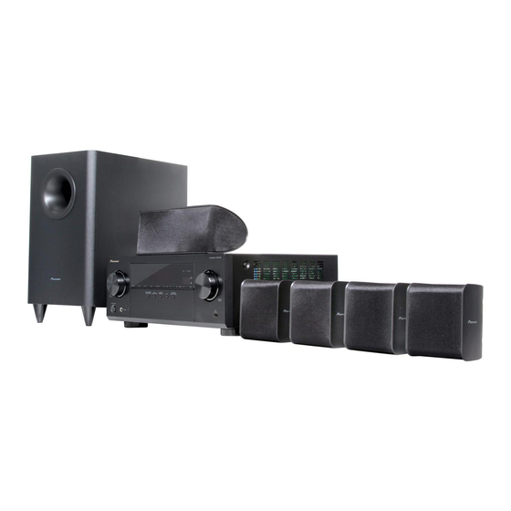
Page 1: Speaker System
————— S-11A-P ————— ————— HTP-072 and HTP-073 is a Home Cinema Package and consists of VSX-324-K-P, S-22W-P and S-11A-P. PIONEER CORPORATION 1-1, Shin-ogura, Saiwai-ku, Kawasaki-shi, Kanagawa 212-0031, Japan PIONEER ELECTRONICS (USA) INC. P.O. Box 1760, Long Beach, CA 90801-1760, U.S.A. -
Page 2: Safety Information
PIONEER Service Manual. A subscription to, or additional copies of, Also test with plug reversed Earth PIONEER Service Manual may be obtained at a nominal (Using AC adapter ground charge from PIONEER. plug as required) -
Page 3: Table Of Contents
11.3 AMP6 ASSY ................................82 11.4 CPU ASSY.................................. 84 11.5 FRONT, INSEL, HP and FUSB ASSYS ........................86 11.6 CNT ASSY.................................. 88 11.7 STBY ASSY................................89 11.8 V_SEL, G-L, G-T and G-CNT ASSYS ........................90 12. PCB PARTS LIST ................................91 HTP-072... -
Page 4: Service Precautions
—————— IC with heat-pad IC2214 D-MAIN 5 V Power Supply IC —————— IC with heat-pad IC400 ADJUSTABLE LDO REGULATOR J126238700010-IL IC with heat-pad 1.3 SERVICE NOTICE • Discharging For more detail, please refer to "7. DISASSEMBLY - 1. Discharging". HTP-072... -
Page 5: Specifications
Dimensions....435 mm (W) x 168 mm (H) x 362.5 mm (D) Weight (without package) ............7.5 kg Maximum power output (Front, Center, Surround) ..........110 W per channel (1 kHz, 6 Ω, 10 %) Guaranteed speaker impedance ........6 Ω to 16 Ω Video section Signal level Composite ..............1 Vp-p (75 Ω) HTP-072... - Page 6 Non-skid pads x 20 (8952S11005510-IL) Dry cell batteries Operating instructions (CD-ROM) (YXE8, VYXE8, PWXE only) (AAA size IEC R03) x2 (HTP-072/YXE8, VYXE8, PWXE: 6517000001380-IL) (HTP-073/VYXE8: L068250160020-IL) Quick start guide (YXE8, VYXE8, PWXE only) FM wire antenna (HTP-072/YXE8, VYXE8, PWXE: 5707000008050-IL)
-
Page 7: Basic Items For Service
GGD1850 Diagnosis (D-MAIN Assy ↔ CNT Assy) Board to board extension jig cable GGD1851 Lubricants and Glues List Name Part No. Remarks Silicon grease GEM1057 Refer to "9.2 VSX-324-K-P SECTION". Silicon adhesive GYA1011 (KE40RTV-W) Refer to "9.2 VSX-324-K-P SECTION". HTP-072... -
Page 8: Pcb Locations
7028073682050-IL 7028073682010-IL 7028073682030-IL 7028073682040-IL 7028073682010-IL 7028073682020-IL 2.. CNT ASSY (PCB SUB ASSY CNT) 7028073683010-IL 7028073683010-IL 7028073683010-IL 7028073683010-IL 7028073683010-IL 7028073683010-IL NSP 1..PCB TTL ASSY AMP6 7025HK1215074-IL 7025HK1215014-IL 7025HK1215054-IL 7025HK1215044-IL 7025HK1215034-IL 7025HK1215024-IL 2.. AMP6 ASSY (PCB SUB ASSY AMP6) 7028073711010-IL 7028073711010-IL 7028073711010-IL 7028073711010-IL 7028073711010-IL 7028073711010-IL HTP-072... - Page 9 HTP-072...
-
Page 10: Block Diagram
KTC3964 2SB1560 2SB1560 2SB1560 CN712 HP_R HP_GND HP_L HP_DET HP ASSY FRONT ASSY (7028073672020-IL) (7028073671010-IL) CN701 FLAC INSEL ASSY FLCT FLAC GNDU CPU_+3.3V CPU_ST_VCC (7028073674010-IL) 9P WIRE STBY_RLY CPU_ST_VCC CP702 CN702 STBY_KEY STBY_KEY INPUT_UP INPUT_UP GNDU GNDU INPUT_DN INPUT_DN HTP-072... - Page 11 The > mark found on some component parts indicates the importance of the safety factor of the part. Therefore, when replacing, be sure to use parts of identical designation. : The power supply is shown with the marked box. HTP-072...
-
Page 12: Overall Block Diagram
4.2 OVERALL BLOCK DIAGRAM MAIN ASSY AUDIO PART TUNER_L CD_L SAT_L DVD_L TUNER_R CD_R SAT_R DVD_R AIN_R AIN_L Q419 MUTE_B+ UTC4580E IC401 Q426 +12V VOL_DATA VOL_CLK SW_SUM-MC51 D-MAIN ASSY HDMI_IN_1 OPTCO ASS HDMI_IN_2 COAX HDMI_IN_3 HDMI_IN_4 IC2016 HDMI_IN_4 FUSB ASSY USB_D+ USB_D- HTP-072... - Page 13 Q434' SL_FB Q452 SR_FB SR_FB SR_OUT Q458 Q416 FR_FB FR_OUT Q422 MAIN ASSY Q417 (RLY PART) SW_FB SW_OUT Q423 MAIN ASSY OPTCO ASSY (OSD PART) (VIDEO PART) COAX CNT ASSY FUSB ASSY NTSC/PAL X-TAL OPTION NTSC 14M318 PAL 17M734 HTP-072...
-
Page 14: Vcc Block Diagram
MAIN ASSY AUDIO PART +12V V+5V A+6.8V A-6.8V S1(AMP B+/B-) 6.8V 6.8V 2.7A A_-12V ZJ16B ZJ16B MAIN TRANS KIA7805API KIA7812API S2(+12V,-12V) 1.0A KIA7912PI S3(+12V) 2.5A S4(FLT) 0.2A STBY ASSY HL3-1A-6SH STBY_RLY' CORD IL1117-3.3 CPU_ST_VCC M3V3 1N4007 1N4007 JE202B1T2 1N4007 1N4007 HTP-072... - Page 15 DC/DC_3V15 SA1117D-1.2V BD9328 NJM2387 D+3V15 D+3.3V_2 DSP+1.2V DC/DC_ON2 DC/DC_ON1 DSP+3.3V IL1117-5.0 +12V +12V RAQ045P01 RAQ045P01 A_-12V RAQ045P01 A_-12V CPU_ST_VCC SCPU+3.3V NJM2831F33 H+5V D3V3 VCC_3959 3959_PWR USB5V_ON OVER_CURRENT_DET IC2024 NCP380 +12V USB+5V D3V3 M3V3 CPU ASSY OPTCO ASSY FUSB ASSY HTP-072...
-
Page 16: Gnd Block Diagram
4.4 GND BLOCK DIAGRAM AC CORD STBY ASSY MICOM REGILATOR MAIN ASS CEN_A FL_HP FR_HP FL_A FR_A A+12V A+12V POWER TRANS INSEL ASSY HP ASSY HTP-072... - Page 17 D-MAIN ASSY OPTCO ASSY MAIN ASSY CEN_A CEN_A SL_A SR_A FR_A A+12V A+12V A+12V CNT ASSY CPU ASSY A+12V A-12V -HIGHB +HIGHB1 AMP6 ASSY FRONT ASSY FUSB ASSY HTP-072...
-
Page 18: Diagnosis
Check connection betwwern CN705 on FRONT Assy If the connection check is NG, check the FFC cabel (CPU Assy and CN704B on CPU Assy. between CN705 and CN704B or replace the FFC cable. CN704B pins 16, 17) Replace CPU Assy. HTP-072... - Page 19 MAIN Assy. (FRONT Assy C728 - side) replace FRONT Assy. Is the voltage 3.3 V? Check Q702, Q703, R777, R778 (FRONT Assy C730 + side) or replace FRONT Assy. Is damage in FLT701? Replace FRONT Assy. Replace FLT701. HTP-072...
- Page 20 No Problem / No Damage HTP-072: Check connecters between Does HP OUTPUT signal output? MAIN Assy CP5 and HP Assy CN721. (HTP-072: MAIN Assy CP5 pin 2 or 4) Replace MAIN Assy. VSX-323: Check connecters between (VSX-323: MAIN Assy CP101 pin 2 or 4) MAIN Assy CP101 and HP Assy CN721.
- Page 21 Control Check flow for Front ch.) (C_RLY) pin 5 (S_RLY). Select surround mode to EX.STEREO in Advanced Surround . HTP-072: Check signals of problem channel Check signals of problem channel Check signals of problem channel on AMP6 Assy CP401 pin 3 (SL), 5(C), 7(SR).
- Page 22 Check IC1200 on MAIN Assy or Composite in → No Composite out replace MAIN Assy. Rear HDMI in → No HDMI out Replace D-MAIN Assy. Check IC1203, XTAL1200, XTAL1201, Q1207, Q1208, Q1209 on MAIN Assy No OSD or replace MAIN Assy. HTP-072...
-
Page 23: Protection Circuit
NORMAL:3.3V PROTECTION R230FL R2400 ASO PROTECTION:0.83V CIRCUIT R230C DC PROTECTION:1.45V Q2017 R230SR R230SL R2415 R230SW HTP-072 only Q2021 MAIN ASSY POWER DC DETECTION CIRCUIT [2] TEMP Detection Circuit CPU ASSY IC2023 (MAIN CPU) PROTECT2 HEAT SINK MAIN ASSY R2421 R172 NORMAL:3.3V... -
Page 24: Ic Information
Control pin DSP IC +3.3V (on: H) U_CE OSD IC enable signal output and UPGRADE pin 3959_PWR MFI IC Power control pin 3959_RESET MFI IC reset signal VOL_DATA Data signal output for R2A15219 (I2C) VOL_CLK CLK signal output for R2A15219 (I2C) HTP-072... - Page 25 Output for chip enable of SC16315 D+1.8V_ON control pin DSP IC +1.8V (on: H) Ground THRU_LED HDMI LED on/off control pin if Speaker DC protection +3.3 V Power Supply +3.3 V Power Supply STBY_RLY Output to ST-BY Relay ON/OFF (active at H) HTP-072...
- Page 26 Interrupt signal input pin from EP9442 Not used HPD_IN Intput for HDMIOUT HPD Ground SUB_RXD Soft update UART comunication data input pin (UPDATE JIG B'D) SUB_TXD Soft update UART comunication data output pin (UPDATE JIG B'D) HDMI_CEC Data signal input from HDMI_CEC HTP-072...
-
Page 27: Service Mode
DC error." If a protection function is activated immediately after the previous protection function is canceled, cancel that protection function again then enter STBY mode immediately. You can then see the error logs, following the above procedures, until a next protection function is activated. HTP-072... - Page 28 1. When the procedures for Reset mode for numbers of protection detections are completed, all the counters will be reset to "000." 2. Prohibitions: The protection detection counts cannot be cleared (reset to 000) with the MEMORY CLEAR process. They can only be cleared when the procedures of Reset mode are completed. HTP-072...
- Page 29 If the AC power cord is plugged in while the AVR is prohibited from being ON because of DC detection, the HDMI LED will flash at intervals of 500 msec. 3.2 OVERLOAD (overcurrent) error detection Key Operation FL Display Time (sec.) Description of Indications usually Normal display (Normal display) (OVERLOAD detection) (Auto) (RECEIVER POWER OFF) HTP-072...
- Page 30 2 seconds will cancel Key Input Inhibition mode after a DC error detection and turn the unit ON. If the AC power cord is plugged in while the AVR is prohibited from being ON because of DC detection, the HDMI LED will flash at intervals of 500 msec. HTP-072...
-
Page 31: Disassembly
(4) Check that the voltage between the B+ and B– terminals is less than 1 V, using a tester. ∗ Be sure to connect the GND terminal of the tester to the chassis. ∗ If the voltage is still 1 V or higher, repeat Step (3). HTP-072 VSX-323 MAIN Assy B–... - Page 32 (5) Release the two jumper wires. (6) Disconnect the one flexible cable and three CP701 connectors. (CN704B, CP5, CP701, CP2006) CN704B CPU Assy G-L Assy (7) Unhook the two hooks. Front panel section (8) Remove the front panel section. HTP-072...
- Page 33 (CP3, CP205) (5) Remove the heatsink section. CP205 AMP6 Assy MAIN Assy (6) Connect the two extension jig cables. Borad to board extension jig cable (GGD1773) Diagnosis CP205 AMP6 Assy MAIN Assy Borad to board extension jig cable (GGD1628) HTP-072...
- Page 34 (2) Arrange the D-MAIN Assy in the photo below. jig cable (GGD1850) (3) Insert any insulation sheet. CP2001 Diagnosis CP2000 CP2003 CPU Assy CP110 CP100 Assy CP19 Borad to board extension Borad to board extension jig cable (GGD1849) jig cable (GGD1851) HTP-072...
-
Page 35: S-22W-P
(5) Remove the MAIN Assy with CPU Assy and back chassis. CPU Assy MAIN Assy 7.2 S-22W-P Orientation of the Speaker during Attachment Rear Attach the speaker so that the terminals are placed nearer the rear. • Bottom view HTP-072... -
Page 36: S-11A-P
3. Similar procedures for the sides of the opposite end. 4. Disconnect the cable, and then remove the speaker unit. Note: When attaching speaker unit, face its terminal leftward. Use other fingers to support the Use other fingers to Cabinet front. support the Cabinet front. Fig.3 HTP-072... -
Page 37: Each Setting And Adjustment
To confirm if .NET Framework 3.0 Service Pack 1 has been installed on your PC or not, select Settings > Control Panel > Add or Remove Programs. This confirmation method may be different, depending on the PC. Refer to the operation manual of the PC you use on how to execute Add or Remove Programs. HTP-072... - Page 38 1 Selection of upgrade file 1 Select the update file 3. Press the OK button. Press the OK button. Select "VSX324 Main V1xx.mot" file Select for COM port. to update the MCU. 2 Enter ID. Press the OK button. HTP-072...
- Page 39 3. Holding down the tact switch (RESET) of the Upgrade Jig in AC OFF state. Release the tact switch after AC ON, power ON (2-3 seconds later). Select the 9600 of the Board rate then press the OK button HTP-072...
- Page 40 Each time the " ENTER "key is pressed, then indications on the FL display change as follows: "ENTER" "ENTER" "ENTER" "ENTER" MAIN Ucom SUB Ucom All segments lit. DSP firmware MAIN Xx.xx SUB zzz.zz CEC Vy,yy "ENTER" 2. Turn the unit off. HTP-072...
- Page 41 4. After playback is finished and "ENTER" is displayed, press the ENTER key on the front panel. ("ENTER" is displayed.) 5. "WRITING" is automatically displayed. 6. After writing is completed, "COMPLETE" is displayed. 7. Turn the unit off then confirm that the version has been updated. HTP-072...
-
Page 42: Exploded Views And Parts List
AXQ5 only AXQ5 only YXE8, VYXE8, PWXE only ×4 CMXESM, DLXE, AXQ5 only ×20 YXE8, VYXE8, PWXE only Dry cell batteries CMXESM, DLXE, AXQ5 only VYXE8, DLXE only S-22W-P Poly bag Style Tape (100 x 180) Front (Clear) (Side) HTP-072... - Page 43 See Contrast table (2) 14 Operating Instructions See Contrast table (2) 15 Operating Instructions See Contrast table (2) (2) CONTRAST TABLE HTP-072/CMXESM, YXE8, VYXE8, DLXE, PWXE, AXQ5 and HTP-073/VYXE8 are constructed the same except for the following: Symbol and HTP-072 HTP-072 HTP-072...
-
Page 44: Vsx-324-K-P
9.2 VSX-324-K-P DLXE only HP plate Clamp HTP-072... - Page 45 CMXESM, YXEB, PWXE AXQ5 only VYXEB, DLXE only DLXE only ×23 Binder Binder Binder Binder Silicon adhesive (GYA1011) Binder Heatsink Silicon grease (GEM1057) HTP-072...
- Page 46 23 Cable, Flat Card 1.0 N711251022480-IL 54 Screw Tapping Assy B018230141H11-IL 24 CN, Wire See Contrast table (2) 55 Screw, Tap Tite B020230063B10-IL 25 Pioneer Badge B (PLS) XAM3006 56 Screw B028940101B11-IL 26 Cabinet Assy 3008211846020-IL 57 Screw 1500001206010-IL 27 Front Panel 324...
-
Page 47: S-22W-P
S-22W-P SECTION PARTS LIST Mark No. Description Part No. 1 Unit Assy 8952S22W00009-IL 2 Network Assy 8952S22W00011-IL 3 Speaker Terminal 8952S22W00004-IL 4 Foot Mold 8952S22W00007-IL 5 Foot Cushoin 8952S22W00200-IL 6 Cashmere 8952S22W00210-IL 7 Screw (Bind Head) 8952SHM700039-IL 8 Screw (Bind Head) 8952S21W05381-IL HTP-072... -
Page 48: S-11A-P
9.4 S-11A-P Front L, R, Surround L, R speaker Center speaker HTP-072... - Page 49 Center speaker 1 Unit Speaker (Front) 8952S11005090-IL 2 Speaker Wire 8952S11005140-IL 3 Speaker Terminal 8952S11005100-IL 4 Frame Net Assy 8952S11005030-IL 5 Case Rear Assy 8952S11005060-IL 6 Felt 8952S11005411-IL 7 Cassimere 8952S11005130-IL 8 Screw 8952SB3001110-IL 9 Screw (Bind Head) 8952S11005150-IL HTP-072...
-
Page 50: Schematic Diagram
2K2(1) 2K2(1) 2K2(1) 10/50 KSA916Y 4R7(1) 22(1/4) 1N4007 RT1P237C RT1P237C RT1P237C RT1P237C D10SB60 FROM RT1N237C RT1N237C RT1N237C RT1N237C TO CHASSIS TRANS C66 - GND4 R172 ZD101 D107 LBAS16HT1G LUDZS3.3BT1G CP100 6 7 8 9 10 5267-03A POSISTOR CN204 CP203 HTP-072... - Page 51 C1254 100N-K CP14 U/DGND MUTE_B+ U/DGND U/DGND C298 SURL 10N-K Q130 KSA992F DC_PRO R294 U/DGND -VF(-30V) -VF(-30V) HP_RLY HP_DET VOL_DATA VOL_CLK SW_SUM A_MUTE KSA916Y 4R7(1) THER_DET 2(1/4) MAIN ASSY (CMXESM: 7028073701040-IL) (YXE8, VYXE8: 7028073701010-IL) (DLXE: 7028073701030-IL) (PWXE, AXQ5: 7028073701020-IL) HTP-072...
-
Page 52: Main Assy (2/3)
C519 33P-J Q425 R566 R565 470K 2SK209Y R568 C556 2SK209Y Q426 C520 33P-J RT1P141C C522 33P-J R569 R571 91K R572 RT1P141C R573 10K RT1N441C R576 R574 10K C557 R577 Q428 2SK209Y C529 C528 10N-K 10N-K R609 470K R610 470K HTP-072... - Page 53 J415 (SL) : Audio Signal Route (Surround L ch) J402 : Audio Signal Route (Center ch) (SW) : Audio Signal Route (SubWoofer ch) (TU) : Audio Signal Route (Tuner L ch) (CD) : Audio Signal Route (CD L ch) HTP-072...
-
Page 54: Main Assy (3/3)
1N4007 R283 0R22(1) D119 1N4007 VGND RLYGND F100 D121 KBPC8005_8A 0R22(1) FROM R284 TRANS 0R22(1) R286 CP2200 • NOTE FOR FUSE REPLACEMENT CAUTION - FOR CONTINUED PROTECTION AGAINST RISK OF FIRE, REPLACE WITH SAME TYPE AND RATINGS OF FUSE. HTP-072... -
Page 55: Optco Assy
(7028073702010-IL) IC1201 L107 SN74AHCU04PWR C273 L110 L108 C272 R272 2.2UH BD121T 100N-K BD121T 22P-J JACK105 RCA-107A R182 R271 C275 100N-K C271 R273 C276 330P-J 10N-K R300 CP108 R301 R303 C295 C294 R302 R181 BKT102 JACK104 L106 4.7UH C270 BCR-802-M25 HTP-072... -
Page 56: D-Main Assy (1/3)
RX12+ R2075 RX22- IC2001 R2038 TIMI EPF025A RX22+ TIMO HT3_CNTB HT2_CNTB HT1_CNTB HT0_CNTB HT3_CNTB R2044 R2027 R2043 R2023 510K DDC3_SDA DDC3_SCL CEC_OUT RXC3- R2061 RXC3+ XTAL2000 R2062 RX03- 24MHZ-15pF SUB_RXD R2064 SUB_TXD RX03+ RX13- RX13+ RX23- H+5V RX23+ R2077 HTP-072... - Page 57 CPU_+3.3V Q2038 RT1N141C THRU_LED THRU_LED HDMI_SEL HDMI_SEL CB2014 CB2015 USB5V_DET USB5V_DET CPU_ST_VCC USB5V_ON USB5V_ON CB2010 DSP_RST DSP_RST DSP_RDY DSP_RDY R2082 IC2004 DSP_CS NJM2831F33 DSP_CS DSP_SOMI DSP_SDOUT DSP_SDA DSP_SIMO DSP_SCL DSP_SPICLK SUB_OPO SUB_OPO SUB_RXD SUB_RXD SUB_TXD SUB_TXD HDMI_IO33 D2062 H+5V HTP-072...
-
Page 58: D-Main Assy (2/3)
L2205 C2403 C2407 C2420 C2406 BD9328 100N-K 10P-D 100N-K 10P-D 1208.08 9329 -> 9328 C2426 GRM31CB31E106KA75L GRM31 C2422 GRM31CB31E106KA75L C2384 GRM31 100N-K C2405 330P-J C2412 10P-D C2383 330P-J C2413 1N-J C2391 100/25 C2414 100N-K C2392 100P-J CP2200 5268-04A CN112 HTP-072... - Page 59 R1416 330P-J Vo=Vref(1+R2/R1) C2413 1N-J C2414 100N-K (FL) : Audio Signal Route (Front L ch) (SL) : Audio Signal Route (Surround L ch) : Audio Signal Route (Center ch) GND_OPTION (SW) BKT2001 : Audio Signal Route (SubWoofer ch) N112 HTP-072...
-
Page 60: D-Main Assy (3/3)
R2194 AXR1[5] DAI_LRCK IIS_SCLK C2199 DVdd DAI_BCK 100N-K R2200 AXR1[4] R2219 AXR1[3] R2220 AXR1[2] R2221 IIS_SCLK AXR1[1] IIS_SD0/DSD0_L R2222 DAI_SD0/DSD0_L IIS_SD3 IIS_SD3 IIS_SD2 IIS_SD2 IIS_SD1/DSD0_R IIS_SD1/DSD0_R SDIN4SB SDIN3C SDIN2S SDIN1F R2228 R2225 R2479 Q2011 3959_PWR RT1N144C R2325 Q2010 ISA1530AC1 HTP-072... - Page 61 EMA_WE 100N-K EMA_D[7] C2244 100N-K DVdd 47:DVdd EMA_D[6] C2245 1000P 46:EMA_D12] EMA_D[5] L2032 R2308 45:EMA_D[1] CVdd BD121T C2246 EMA_D[4] 100N-K IC2019 EMA_D[3] W25Q32VSSIG C2247 100N-K R2293 SO/SIO1 HOLD# SCLK SI/SIO0 R2288 R2289 /EMU1 /EMU0 R2479 C2249 10N-K /TRST FPC2001 HTP-072...
-
Page 62: Amp6 Assy
Q204SL R204SL C214FL 2SC3964 C214SL C214C C214SR R208SL C239 47(1/4) C214FR Q206SL Q203SL R219SL C214SW KTC3206Y 2SB1560P C225SL (SL) HTP-072 ONLY C201C 10/50 R201C 2SD2390P R218SW Q205SW C207SW 470K 47(1/4) R224SW R205SW C229SW 47/50(6.3*11) C212SW Q207SW 82P-100V C213SW C204SW 82P-100V... - Page 63 R206FL 10/50 (FL) 820P Q202FL R214FL R201FL KSA992F R229 (SL) (FL) Q201FL KSA992F Q204FL R204FL C215 2SC3964 4.7/50 VSX-323 R208FL HTP-072 R219FL Q206FL D202 Q203FL 47(1/4) 2SB1560P 1N4148 KTC3206Y HTP-072 ONLY CP205 C225FL (SL) 2SD2390P C207C R218C 47/50(6.3*11) Q205C 47(1/4)
-
Page 64: Cpu Assy
R2335 R2313 R2332 C2285 10/16 MUTE_B+_CTL Q2013 RT1N237C R2345 R2338 R2314 100K C2277 100N-K R2333 ZD2001 UDZ3.3B C2287 Q201 R2312 2.2/50 2SC305 R2336 C2286 10N-K 1N-K C2280 MAIN MICOM UPGRADE 1.0-11S-10PW FPC202 BACK CHASSIS 3P WIRE CP13 CP14 CP205 HTP-072... - Page 65 R2336 R2387 R2451 100K ASO_DET' R2421 1 2 3 4 Q2025 2SC3052 R2453 C2286 C2306 10N-K C2311 10N-K 10N-K DC_DET' DC_DET' THER_DET ASO_DET DC_DET3 DC_DET4 CPU ASSY (CMXESM: 7028073681070-IL) (DLXE: 7028073681040-IL) (YXEB: 7028073681010-IL) (PWXE: 7028073681030-IL) (VYXE8: 7028073681050-IL) (AXQ5: 7028073681020-IL) HTP-072...
-
Page 66: Front, Insel, Hp And Fusb Assys
C754 R782 R781 1N-K SW715 STBY_KEY STBY_KEY PRESET+ ENTER AUTO SU R783 INPUT_UP INPUT_UP GNDU GNDU INPUT_DN R784 INPUT_DN C757 820P-K C744 1N-K C745 330P-J C741 100P-J C764 C763 1N-K LUG705 C739 1N-K INSEL ASSY (7028073674010-IL) CN705 1.0-11S-25 CN704B HTP-072... - Page 67 0.8V 1.37V 1.85V 2.23V 2.53V R774 R775 R776 R771 R772 R773 SOUND SOUND PRESET+ ENTER AUTO SURR ADVANCED STANDARD RETRIEVER AIR RETRIEVER LUG701 R3000 1P/100mm 0-1608 R3001 CN2006 0-1608 330MM/5P JACK3000 USB+5V R3010 GNDUSB C765 GNDUSB R3011 PT706 PLATE HTP-072...
-
Page 68: Cnt Assy
4N7-K UTC4580 +12V R602C C604C 470P-J C2402 10/16 C602C 1N-K R603C R601C C2338 82P-J R600C IC605A C2361 C601C UTC4580 1N-K 4N7-K C604SW R602SW 470P-J (SW) 10/16 C602SW R601SW R603SW C2339 82P-J R600SW C601SW C260 - IC605B 4N7-K UTC4580 C261 HTP-072... - Page 69 C2346 82P-J +12V +12V +12V C2347 -12V 82P-J -12V -12V (FL) : Audio Signal Route (Front L ch) (SL) : Audio Signal Route (Surround L ch) : Audio Signal Route (Center ch) (SW) : Audio Signal Route (SubWoofer ch) HTP-072...
-
Page 70: Stby And V_Sel Assys
F301 FUSE CP102 LWBP1143-05P 220-2 110-127 , 220-240V 220-2 (DLXE) CN103 T3.1 T6.3AL250V F301 FUSE 220-23 DLXE ONLY 110-127 , 220-240V (DLXE) 220-2 120V(CMXESM) T6.3AL250V T3.1 • NOTE FOR FUSE REPLACEMENT CAUTION - FOR CONTINUED PROT REPLACE WITH SAME T HTP-072... - Page 71 TRANS FLAC 220-230V(SYXE8) 110-127 , 220-240V 220-240V(PWXE) CP304 (DLXE) 5267-03A T3.15AL250V T6.3AL250V F301 FUSE 220-230V((V)YXE8) 110-127 , 220-240V (DLXE) 220-230V(PWXE) 120V(CMXESM) 220V(AXQ5) T6.3AL250V T3.15AL250V REPLACEMENT CONTINUED PROTECTION AGAINST RISK OF FIRE, ACE WITH SAME TYPE AND RATINGS OF FUSE. HTP-072...
-
Page 72: S-11A-P
P.SW heats up and the resistance rapidly increases. With this function, the speakers are protected from excessive input or unusual signal. The resistance value increases even when using a soldering iron for repairing, so allow it to cool before using. HTP-072... - Page 73 HTP-072...
-
Page 74: Pcb Connection Diagram
11. PCB CONNECTION DIAGRAM 11.1 MAIN and OPTCO ASSYS SIDE A MAIN ASSY HTP-072 MAIN STEP : MP 7020-07370-000-0S JP33 3*17 JP65 JP31 JP32 JP35 JP50 FRONT RE JP79 RLY3 OPTCO ASSY JZC-42F RLY2 JP58 JZC-42F JP103 JP37 RLY4 JZC-42F 3*17 1. - Page 75 (16*25) Q130 C279 D125 JP177 JP84 JP44 R293 C288 R279 1000/25 R299 (10*20) R290 R294 C296 C292 10000/16 (18*35) C231 R286 JP105 R283 R284 D121 KBPC8005-8A CN112 CP113 CP109 CP110 CP100 CP113 CN112 CP115 CP2200 TRANS POSISTOR TRANS IC1203 HTP-072...
- Page 76 SIDE B MAIN ASSY CN112 CP113 CP100 CP110 CP109 Q415 Q1207-Q1209 IC1200 Q1210 IC400 Q416 Q9-Q12 Q2-Q5 Q414 IC401 Q1216 IC402 IC403 Q417 Q14-Q16 IC408 Q419 Q425-Q428 HTP-072...
- Page 77 SIDE B OPTCO ASSY CP108 IC1201 Q2-Q5 Q14-Q16 HTP-072...
-
Page 78: D-Main Assy
11.2 D-MAIN ASSY SIDE A D-MAIN ASSY CP108 CN112 CP2003 CP2006 CP110 CN2006 HTP-072... - Page 79 SIDE A Q2007 Q2006 Q2005 Q2003 Q2001 Q2002 Q2029 IC2026 IC2001 IC2012 Q2028 IC400 CP19 Q2010 IC2214 IC2017 Q2011 IC2013 IC2004 IC2015 CP100 IC2207 IC2019 IC2014 IC2209 Q2037 HTP-072...
- Page 80 SIDE B Q2038 Q2043 Q2041 IC2018 HTP-072...
- Page 81 SIDE B D-MAIN ASSY CP2006 CP2003 HTP-072...
-
Page 82: Amp6 Assy
R218C J302 J306 J305 C209C C209FR C210C C210FR C209SR C210SR R214FR R214C R214SR Q202FR Q201FR Q202SR Q201SR Q202C Q201C Q208 Q207FR Q203FR Q207SR Q203SR Q207C Q203C Q205FR Q204FR Q206FR Q205SR Q205SR Q206SR Q205C Q204C Q206C SIDE B CP205 CP203 HTP-072... - Page 83 J304 C209FL C210C C209SW C209SL C210FL R214SW C210SW R214SL R214FL C210SL Q202SW Q201SW Q202SL Q201SL Q202FL Q201FL Q207SW Q203SW Q207SL Q203SL Q207FL Q203FL Q206C Q205SW Q204SW Q206SW Q205SL Q204SL Q206SL Q205FL Q204FL Q206FL SIDE B AMP6 ASSY CP201 CN204 HTP-072...
-
Page 84: Cpu Assy
SIDE A SIDE A CPU ASSY CP13 CP 3 1 TUNER_INT 2 TUNER_SDIO 3 TUNER_SCLK 4 TUNER_SEN CP2001 5 TUNER_RST 6 OSD_RST 7 OSD_CE 8 OSD_CLK 9 OSD_DATA 10 V_CTL_A 11 V_CTL_B 12 VIDEO_MUTE 13 V+5V CP2000 CP14 CP205 CN705 HTP-072... - Page 85 SIDE B SIDE B CPU ASSY IC2020 Q2012 IC2023 Q2013 Q2014 IC2022 Q2023 Q2025 Q2020 Q2022 Q2021 Q2019 Q2016 Q2017 Q2018 HTP-072...
-
Page 86: Front, Insel, Hp And Fusb Assys
11.5 FRONT, INSEL, HP and FUSB ASSYS SIDE A CP701 FRONT ASSY INSEL ASSY CN701 9 PIN FLBKT2 FLBKT1 VEC702 CN702 Q702 SW715 SIDE B INSEL ASSY Q707 Q701 Q703 IC701 CN702 CN701 FRONT ASSY HTP-072... - Page 87 SIDE A CN704B HP ASSY CN705 CN721 CN705 FLBKT2 CP2006 CN2006 JACK3000 FUSB ASSY SIDE B FUSB ASSY Q706 Q708 Q704 Q709 CN2006 HP ASSY CN705 CN721 F H I HTP-072...
-
Page 88: Cnt Assy
11.6 CNT ASSY SIDE A SIDE B CNT ASSY CNT ASSY CP2003 CP110 CP110 OPEN OPEN OPEN OPEN OPEN OPEN JUMPER JUMPER CP115 CP115 CP110 IC603 IC604 IC605A HTP-072... -
Page 89: Stby Assy
CN901W1 TRANS ZJ5.1B OPTION (ZJ4.7B - DLXE ONLY) PT301 STBY TRANS (S)(V)YXE8 PWXE 8200-28015-068-0S AXQ5 CMXEMS 8200-28015-062-0S DLXE 8200-28015-069-0S CP303 CP302 DLXE CN102 CN103 ONLY SIDE B SIDE B STBY ASSY CP303 CP302 CP701 CP304 Q303 IC301 Q302 Q301 HTP-072... -
Page 90: V_Sel, G-L, G-T And G-Cnt Assys
J610 J602 CN103 CP102 J607 J601 CN103 CN102 CN102 CN103 CP302 CP303 DLXE ONLY G-L ASSY G-L ASSY HTP-072 GUIDE_L PCB 7020-07370-000-0S PIONEER G-T ASSY G-T ASSY HTP-072 GUIDE_TRANS PCB 7020-07370-000-0S PIONEER G-CNT ASSY G-CNT ASSY GUIDE_CNT PCB 7020-07370-000-0S PIONEER... -
Page 91: Pcb Parts List
7028073701020-IL X1200 Crystal (14M32) E80014R318080-IL Not used E80014R318080-IL E80014R318080-IL X1201 Crystal (17M734) Not used E80017R734410-IL E80017R734410-IL E80017R734410-IL Tuner, FM/AM E903004100780-IL E903104100780-IL E903004100780-IL E903004100780-IL Note: This list is not complete. Only components that are available as service part are listed! HTP-072... - Page 92 X 1200 CRYSTAL (14M32) E80014R318080-IL SEMICONDUCTORS CN 9001 CONNECTOR L108353280360-IL IC 400 J126238700010-IL CN 9013 CN,WAFER L109012511320-IL IC 2001 8952523000020-IL CN 9014 CN,WAFER L109012511920-IL IC 2004 J126283133010-IL IC 2014 J040742570040-IL CN 9110 CN,WAFER L109012512320-IL IC 2018 J001986466010-IL TUNER,FM/AM E903004100780-IL IC 2019 8952523000030-IL HTP-072...
- Page 93 FUSE GLASS TUBE 20MM (T3.15AL/250V) N751503151160-IL G-L ASSY INSEL ASSY There is no service parts. MISCELLANEOUS S 9702 SW,ENCODER G121121200230-IL G-T ASSY There is no service parts. HP ASSY MISCELLANEOUS G-CNT ASSY JA 701 JACK,D6.5 G402PJ612A09Y-IL There is no service parts. HTP-072...